Projects:2014S1-33 Software-Defined Radio for VLF Transmission
Contents
Introduction
Environmental sensing is an emerging industry which will shape and support human activities. Large sensor networks exist to gather vital soil information such as soil moisture and salinity. Wired communication between sensor nodes is very cumbersome and infrastructure heavy. In contrast, standard wireless protocols in the microwave region require significant power and reduce battery life. In this project, the Very Low Frequency (VLF) range (30 kHz) has been sought as an alternate method of transmission. Additionally, Software-defined Radios (SDRs) have been used for both the transmitter and receiver. The use of an SDR allows for reduced hardware complexity and lower power consumption. Digital and analogue circuitry, a loop antenna and software have all been addressed to construct the system.
Project Background
What is VLF?
- Standard defined by International Telecommunication Union (ITU)
- Frequency range 3 kHz to 30 kHz
- Wavelengths from 10 Km to 100 Km
What is an SDR?
- Radio components implemented in software
- Digital components replace analogue
- Interface with analogue world
- ADC and DAC conversion
- Processing takes place in digital domain
- Adaptable and customisable
- Wide range of applications
- Ideally support:
- Any waveform
- Any carrier frequency
- Any bandwidth
- Any modulation technique
The Significance
- Re-configurable
- Upgradable
- Software re-use and duplication
- Adaption to environment
- Significantly lower power requirements than traditional radio
Project Scope
- New project in 2014
- SDR for VLF transmission
- Conduct a proof of concept
- Design and verify software algorithms
- Implement software onto Microcontroller
- Design, build and test analogue circuitry
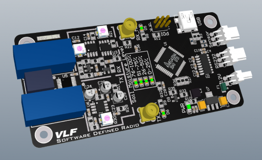
- Implement SDR onto PCB
- Integrate SDR, RF Front End, Antenna and Soil Sensor
System Overview
Hardware
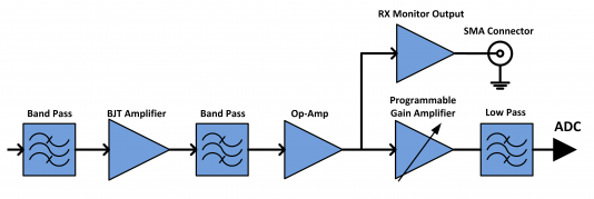
Below is a block diagram of the Hardware subsystem.
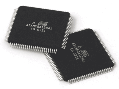
The micro-controller being used is an Atmel XMEGA AU Microcontroller. The AVR Xmega microcontrollers is a family of low-power, high-performance, and peripheral-rich CMOS 8/16-bit microcontrollers based on the AVR enhanced RISC architecture. It is being used to transmit and receive the data.
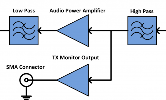
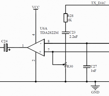
Transmission path starts from the Digital to Analogue Converter (DAC) output of the micro-controller. It is filtered and passed through an amplifier to make it suitable for transmission.
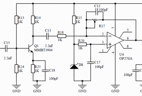
Receiver path starts from the antenna. It goes through various filtering and amplifying stages before being sampled by the Analogue to Digital Converter (ADC) on the micro-controller.
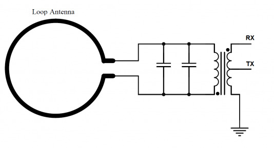
The Antenna Coupling section includes the impedance matching for the antenna. It also includes a RF switch to switch between the Transmission and Receiver paths.
Software
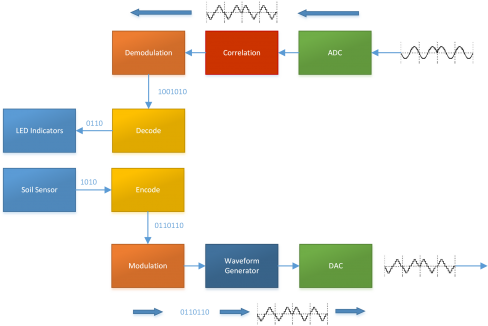
Below is an overview of the Software section.
For the receive path, the signal is sampled by the ADC. It is then correlated against a codeword to locate where the data is. This data is then passed through the demodulate module which will extract the data embed in the phase changes of the signal. It is then passed through the decoding module which will perform error correction and output the moisture sensor data.
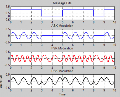
The modulation scheme was chosen to be Phase-shift Keying (PSK) over Amplitude-shift Keying (ASK) and Frequency-shift Keying (FSK).
Personnel
Team Members
- Mr. Matthew Baronian
- Mr. Alex Coleman
- Mr. Jock Duncan
Supervisors
- Dr. Thomas Kauffman
- Prof. Christophe Fumeaux
