Projects:2015s1-50 Tracking, Herding and Routing by Autonomous Smart Cars (PG)
Contents
Introduction
The rapidly increasing of the vehicles becomes a reason for traffic accident today. Although the vehicle provides a more convenient way to travel, people may waste more time on the road. Additionally, the long-time driving make driver tired which is also a factor of traffic accident. In this case, many companies are ready to research and develop the smart car, which can drive without people and avoid obstacles or achieve some simple tasks intelligently.
Team Members
- Mingnan
- Ke Cai
Supervisors
- A/Prof Cheng-Chew Lim
- Prof Peng Shi
Hardware Overview
(1)The Arduino robot:
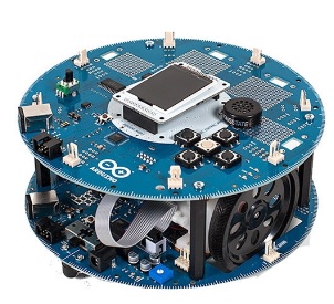
The Arduino Robot is the product of Arduino Company. The robot is the first official Arduino on the wheel. It is consisted by two boards: the control board and the motor board. There are two processors in the robot, which are in the control board and motor board separately. The two boards are programmable by Arduino IDE.
Figure 1: Arduino robot
(2)The webcam:
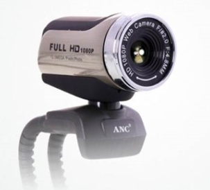
To catch the image and transmit data to the control terminal.
Figure 2:webcam
Software overview
(1)visual studio
The visual studio C++ platform and openCV platform are the perfect products to design all kinds of algorithm. Visual studio is a platform made by Microsoft and it gives engineers to design an algorithm or a simulation, not like Matlab, the C# programing language needs a more complicate steps in mathematic algorithm, but it has a high level of accuracy rate, which means it is more suitable for this project. It can also merge with image processing program language in an easy way.
(2)Arduino IDE
The Arduino IDE is a platform for Arduino robot to make a program on it.
Project result
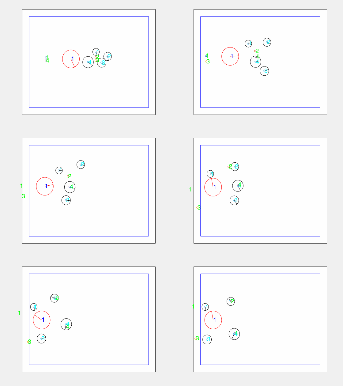
The settled target
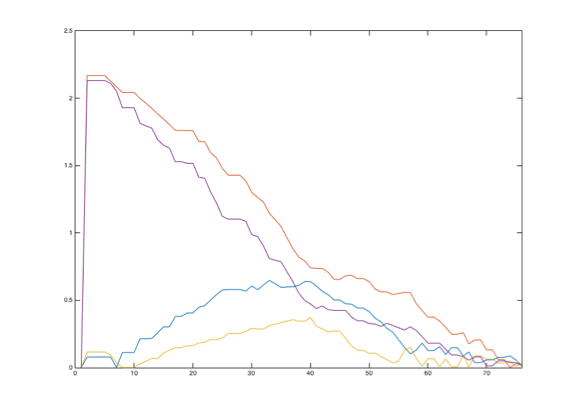
This is the situation to test the algorithm in an easiest way, and the test is focus on the difference between each neighbor angle. The ideal result should be each difference is close to zero eventually.
In this picture, for angle differences have different values at first, during the tracking process, the differences become equally and lead to zero. Four curves all have a gentle changes during this process.
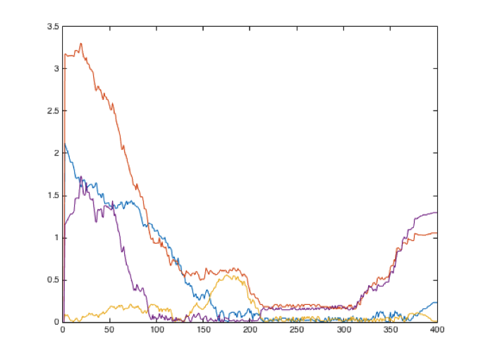
The moving target simulation
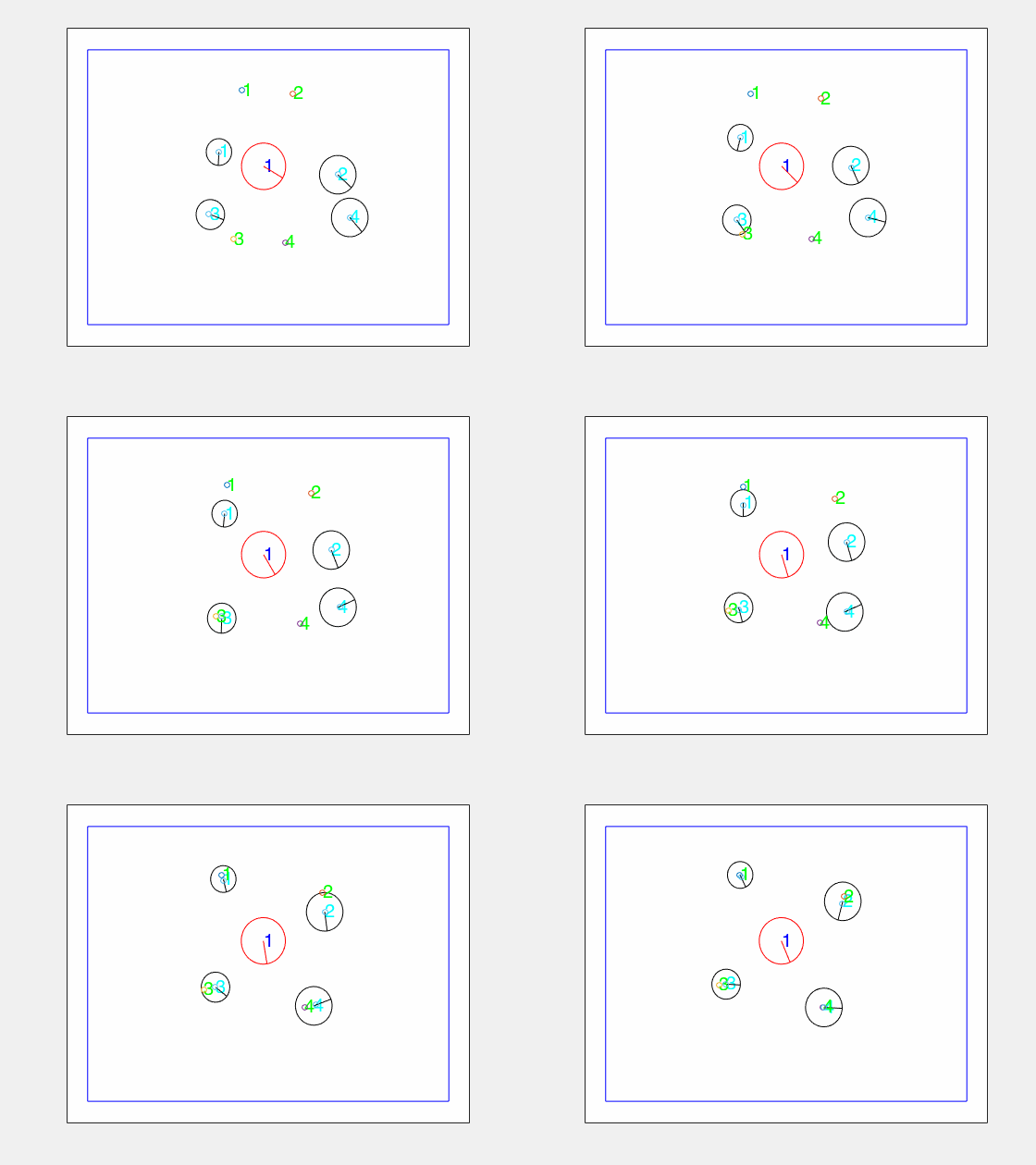
If the target is a moving target, for angle differences will also leads to an equal value and the value will be zero eventually.
It is easy to obverse that these four angles have a huge difference at first, and then lead to an equal value zero. There is a long process to keep this balance, which means the target was surrounded by these tracking cars in safe area in a very long time. Then the target moved to the boundary and it leads the angle differences to become two different values. However, this situation does not happen every time in reality, mostly the target would not have much surround period, which means the balance period would be shorter than the picture above, and the target would not have a balance situation obviously.
Debugging analysis Since this project has a large system, which is contributed by 5 subsystems, even only one error in a subsystem could lead the project shut down. So debugging is significant for this project. But debugging is not only checking the programs and algorithms, but also the system equipment. Meanwhile, debugging needs to be very logical, to cut the system piece by piece and debug them one by one would be an effective way. This project would take a long time for debugging, and here are some debugging analyses for this project:
(1) Image processing:
The image processing is to find the coordinate of each car and put them into algorithm, but there is a time between the first image and the second one, which include two processes, first one is the image processing delay time, the second one is Arduino robot moving time. Sometimes, it is easily to forget Arduino robot moving time and it would lead to many errors.
(2) Head vector:
Head vector is the most important part in this algorithm, it can tell the robot where to go, without the head vector this robot would be blind. Sometimes, Arduino robot have many turning movements, which would lead to a wrong head vector detection since the error of image processing, so make a program to cut this error is also a crucial part in this project.
(3) Print the results:
Since this algorithm have too many steps and logical judgments the error could because of any steps of that, but it is hard to find the wrong part quickly, so the most effective way to solve this problem is to debug the results one by one, set a breakpoint in program to check a part of the program, and print something you made to check the steps.
(4) Set up the threshold value:
An appropriate threshold value is very important for this algorithm. For example, the boundary value, the motor voltage and the height of the webcam are all have a significant influence for this project.
(5) Coordinate system:
Since the coordinate system is not a traditional system just exactly as in mathematic field, so some standard vectors have to adjust the new coordinate system, otherwise it would lead to errors.
Conclusion
This report gives a clear project purpose and content, it introduces all the hardware and software, which has been used in this project. Beside some project managements, it still has not only the outcomes but also many analyzing processes. The improvement advises could help other students with further development. All the achievements in this project can be summarized as below:
• Arduino robot program edition.
• Arduino Wi-Fi shield communication.
• Using visual studio to make a color identification program.
• Appling gyroscope sensor on Arduino robot.
• Using visual studio to design the tracking and routing algorithm of this project.
• Debugging the whole programs and systems.
However, the most important knowledge I have learned is neither an unknown knowledge nor any program editing skills, the most important thing is to learn how to use the limited source and equipment to design a system to achieve the destination. The objective environment might be a limitation, which could lead to a failure. But a wide imagination could help to solve these problems. Do not be afraid of trying, and debugging programs with patience is also necessary.
Reference
[1] Arduino Robot, http://arduino.cc/en/main/robot.
[2] Brown, AS 2011, ‘Google’s Autonomous Car Applies Lessons Learned From Driverless Races’, Mechanical Engineering, Vol. 133, Issue 2, p. 31-31.
[3] Farrell, J 2008, ‘Aided navigation: GPS with high rate sensors’, McGraw-Hill professional engineering, Vol. 124, p. 77-78.
[4] Haitao, J Mei, X 2005, ‘Automatic moving target detecting by a novel video segmentation algorithm’, Proceeding of SPIE, Vol. 5807, p.435-442.
[5] Meyer, G 2011, ‘Advanced Microsystems for Automotive Applications 2011’, Springer, Vol.321, issue 1, p. 21-22.
[6] Norman, S 2014, ‘Google car takes the test’, Nature, Vol.514, Issue 7523, pp. 514.
[7] Johnson, B 2013, ‘Professional Visual Studio 2013’, p. 25-75.
[8] Hao, H, Steven, M, Vittria, C, Alessandro, V, 2009, ‘Wi-Fi network and malware epidemiology’, National Academey of Sciences of the United States of America, Vol.106 (5), pp1318-33.
[9] Mario, N, 2010, ‘Advances in Gyroscope Technologies’, p. 35-60.
[10] Embree, P, 2011, ‘C language algorithm for digital signal processing’, Vol.128, pp1215-90.
[11] Troch, I, Breitenecker, F, 2006, ‘Robot control’, Vol.15 (1), pp. 1-2.
[12] Song, D, 2009, ‘Sharing a Vision Systems and Algorithms for Robotic Cameras’, p. 27-100.
