File list
This special page shows all uploaded files.
| Date | Name | Thumbnail | Size | Description | Versions |
|---|---|---|---|---|---|
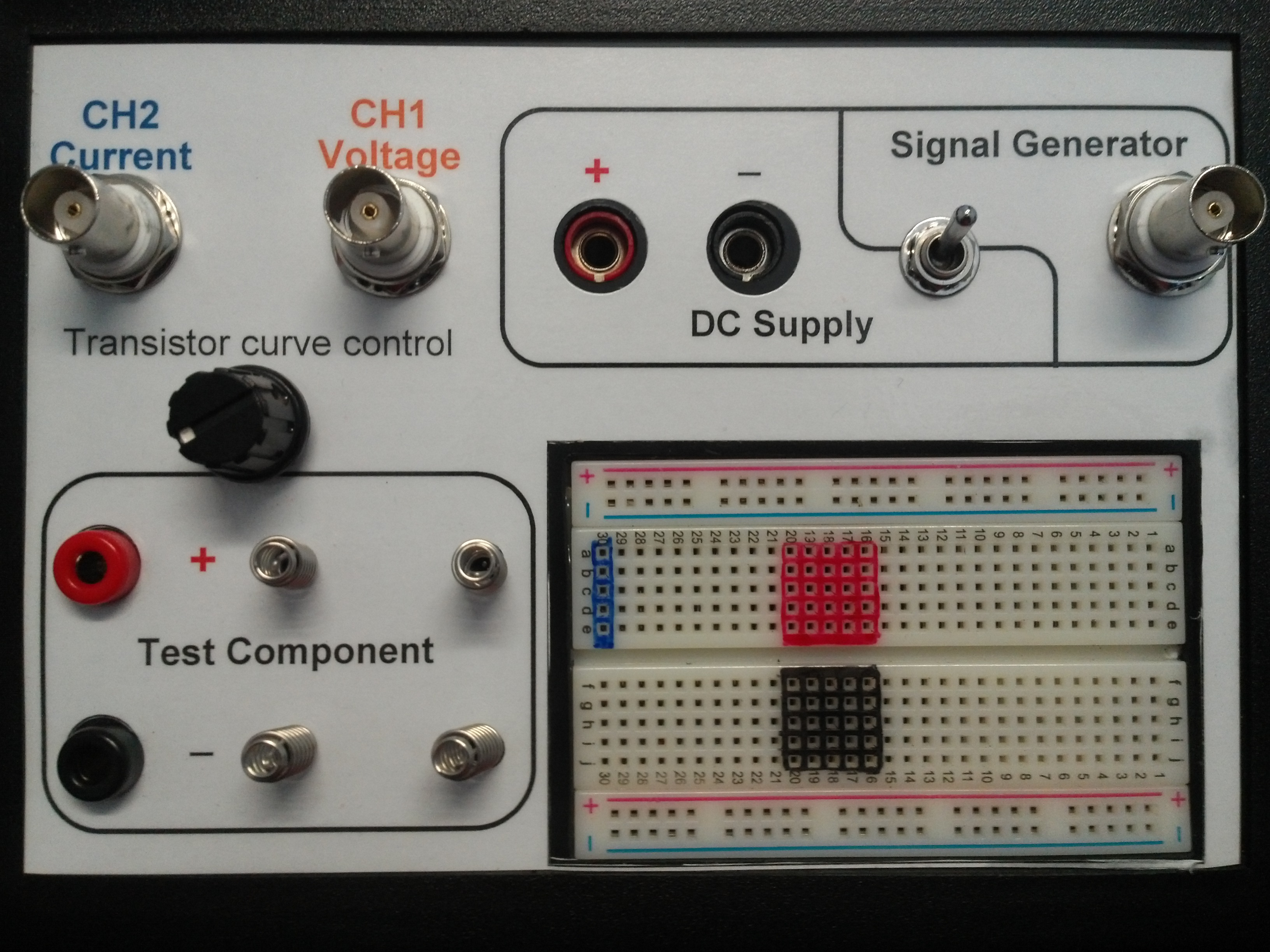
| 13:08, 3 October 2014 | Front panel 2nd.jpg (file) |  |
1.56 MB | The interface layout of the 2nd prototype box | 1 |
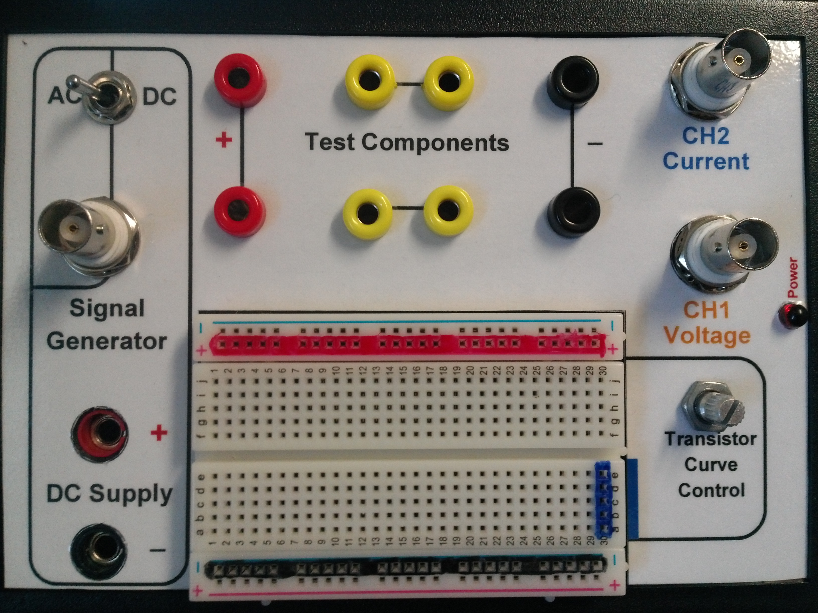
| 13:27, 3 October 2014 | Front panel 1st.jpg (file) |  |
1.44 MB | The interface layout of the 1st prototype box | 1 |
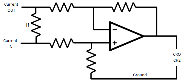
| 13:29, 6 October 2014 | Op-amp circuit.png (file) |  |
10 KB | Circuit for measuring the voltage across the current sense resistor (marked R). | 1 |
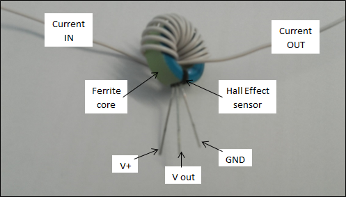
| 13:54, 6 October 2014 | Hall Effect sensor diagram.png (file) |  |
128 KB | Adjusted label positions | 2 |
| 15:15, 6 October 2014 | PCB with components 1st.jpg (file) |  |
717 KB | The first prototype PCB | 1 |
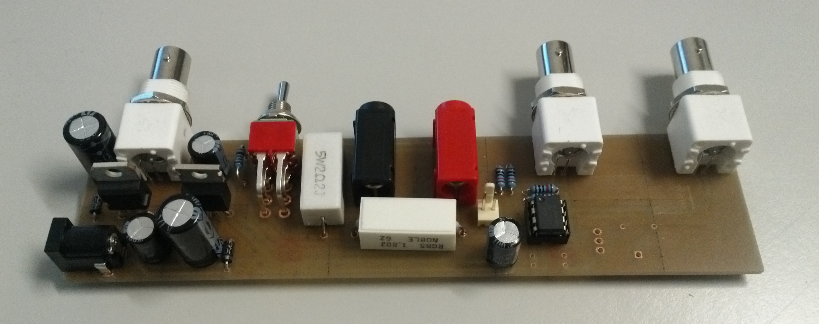
| 15:28, 6 October 2014 | PCB with components 2nd.jpg (file) |  |
824 KB | The seconed prototype PCB | 1 |
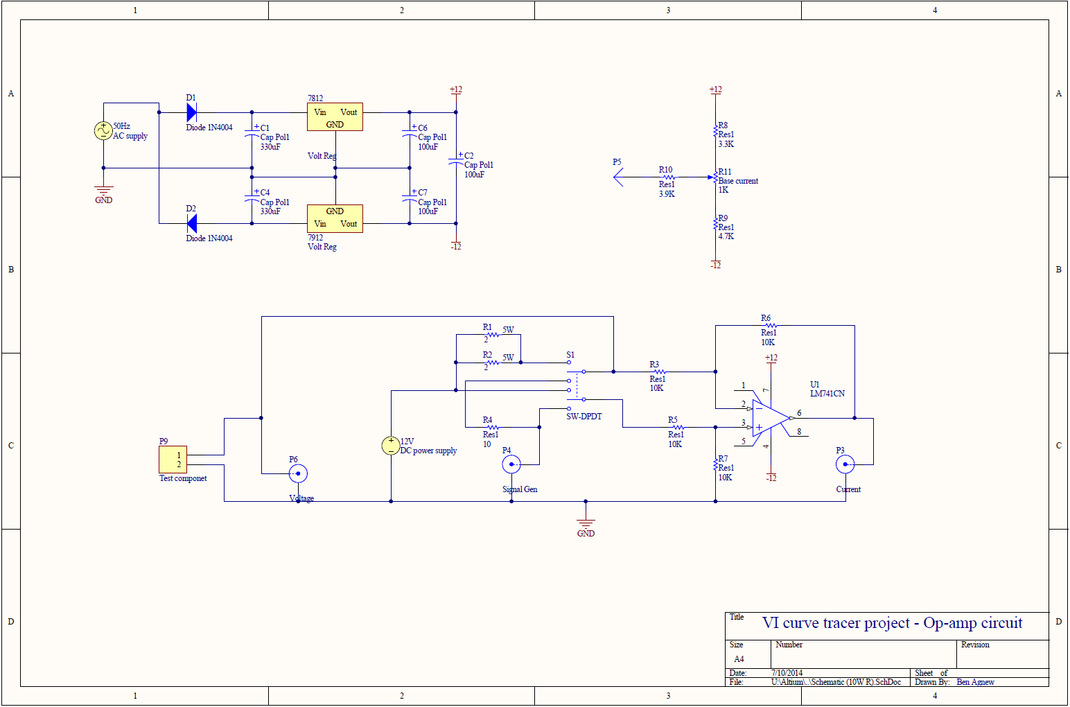
| 10:48, 7 October 2014 | Full op-amp circuit.png (file) |  |
69 KB | Complete op-amp based circuit that was implemented in the prototype boxes | 1 |
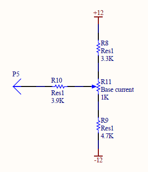
| 15:18, 8 October 2014 | Transistor base circuit.png (file) | 7 KB | Circuit for controlling the gate/base voltage of transistors | 1 | |
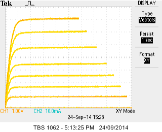
| 15:29, 8 October 2014 | Transistor gate step waveform.png (file) | 12 KB | The drain-source characteristics of MOSFET with a step waveform applied to the gate | 1 | |
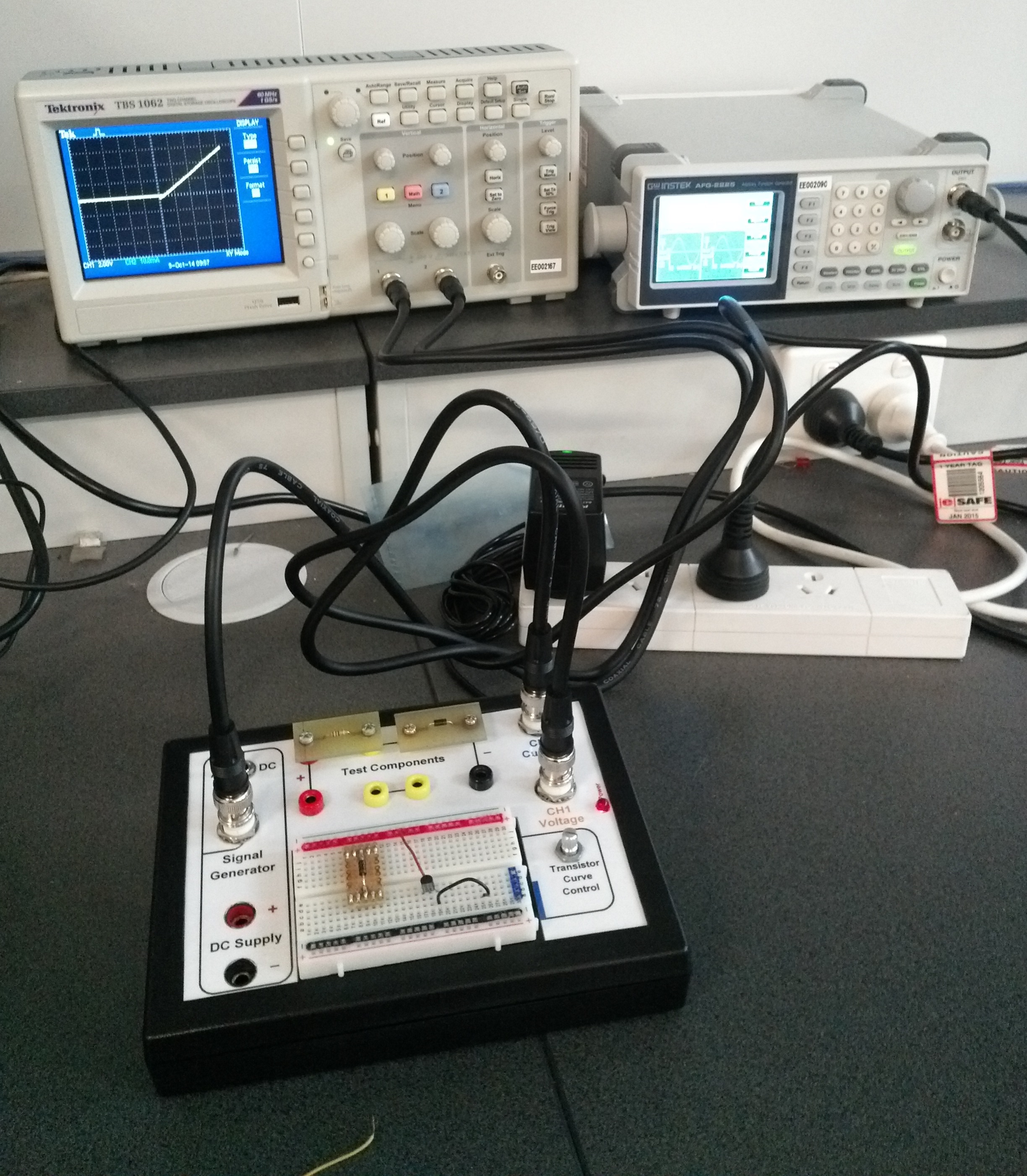
| 15:55, 9 October 2014 | IV tracer experiment.jpg (file) |  |
1.39 MB | The setup for the current-voltage tracer experiment | 1 |
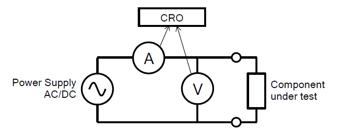
| 18:56, 29 October 2014 | Basic concept diagram.png (file) |  |
12 KB | Updated version | 2 |