Difference between revisions of "Projects:2018s1-113 AVR Test Rig"
| (8 intermediate revisions by the same user not shown) | |||
| Line 12: | Line 12: | ||
Nick Jones (ASC Pty Ltd) | Nick Jones (ASC Pty Ltd) | ||
| + | |||
| + | [[File:ASC.png]] | ||
== Introduction == | == Introduction == | ||
| Line 22: | Line 24: | ||
ASC have approached the School of Electrical & Electronic Engineering at the University of Adelaide with a project that is to design and build a test module for the AVRs. The test module, or "test rig", will allow ASC to quickly and conveniently test and verify the serviceability of the AVRs prior to installation, without the need for a purpose-built facility with a diesel engine and generator set-up. This enables ASC to decrease risk in the form of cost and schedule overruns, by allowing the installation of an AVR that is proven to be in working order. | ASC have approached the School of Electrical & Electronic Engineering at the University of Adelaide with a project that is to design and build a test module for the AVRs. The test module, or "test rig", will allow ASC to quickly and conveniently test and verify the serviceability of the AVRs prior to installation, without the need for a purpose-built facility with a diesel engine and generator set-up. This enables ASC to decrease risk in the form of cost and schedule overruns, by allowing the installation of an AVR that is proven to be in working order. | ||
| + | |||
| + | [[File:Submarine.png]] | ||
| + | |||
| + | === Aim === | ||
| + | |||
| + | The aim of this project is to research and understand the underlying theoretical concepts behind the operation of an AVR for a synchronous generator. These concepts will then be integrated via a series of automated test programs into a physical test rig that will determine whether an AVR is performing correctly with respect to the underlying concepts. The test rig would supply initial excitation voltage to the AVR, allow setting of control parameters and provide feedback signals that replicated the response of the generators (speed, voltage and current). The test rig would be a standalone unit, with a high degree of customisable parameters available to the user, in order to enable the simulation of different generators in different scenarios. The test rig should be provided to ASC as a \proof of concept" package, in which the windings can be easily integrated into readily available hardware to allow them to interface with and test their own unique AVRs, using the knowledge and programming discussed here. | ||
| + | |||
| + | == Mathematical Model == | ||
| + | |||
| + | [[File:Transfer function.jpg]] | ||
| + | |||
| + | ''Figure 1: Generator Transfer Function'' | ||
| + | |||
| + | == Hardware Design == | ||
| + | |||
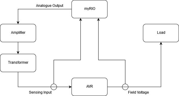
| + | The AVR operates in the 240V range whilst the myRIO reads signals at ±10V. Thus signals need to be conditioned and isolated between the two. The myRIO output varies around 100mV, is then fed into an amplifier to around 5V, is then fed to a transformer, stepping it up to around 240V, and then finally fed to the AVR. The AVR outputs a field voltage varying around 240V which is then fed to a load. A voltage transformer then steps down the signal to around 1V, which is then fed to the myRIO for analysis. | ||
| + | |||
| + | [[File:System_overview11.png]] | ||
| + | |||
| + | ''Figure 2: System Overview'' | ||
| + | |||
| + | == Software Design == | ||
| + | |||
| + | The software used to model the generator was LabVIEW in conjunction with the myRIO. LabVIEW is a graphical programming software and the myRIO is a data acquisition device that has a FPGA and a real-time processor. The myRIO samples two analogue inputs, the sensing voltage and the AVR field voltage. The myRIO monitors the sensing voltage and feeds the AVR field voltage through a transfer function, the generator model, and then feeds the output to the amplifier. The Human Machine Interface is displayed on the host computer, which has some user inputs to vary the parameters of the transfer function and load current in real time. | ||
| + | |||
| + | [[File:AVR output.png]] | ||
| + | |||
| + | ''Figure 3: AVR Output on the HMI'' | ||
| + | |||
| + | == Testing & Results == | ||
| + | |||
| + | Closing the loop provided a system that could feed an input into the AVR and then receive, monitor and then respond to that signal. Varying the user input and graphing the signals allowed a comparison between the expected results and the actual results. | ||
| + | |||
| + | [[File:Simulink.png]] | ||
| + | |||
| + | ''Figure 4: Terminal Voltage response after a load disturbance'' | ||
| + | |||
| + | == Project Achievements == | ||
| + | |||
| + | *Designed and manufactured a closed loop system that can portably test and analyse the AVR response | ||
| + | *Successfully modeled a generator and used it in simulation | ||
| + | *Built a functional program with a user friendly HMI | ||
Latest revision as of 13:37, 17 October 2018
Contents
Project Team
Team Members
Lindsay Millard
Alex Kiddy
Supervisors
Wen Soong
Nick Jones (ASC Pty Ltd)
Introduction
Motivation
ASC Pty Ltd, is an Adelaide based Australian naval shipbuilding company, responsible for the construction of the fleet of six Collins-class submarines (CCSM) for the Royal Australian Navy (RAN) between 1990 and 2003. The company continues to support the fleet through an ongoing maintenance and upgrade program.
The Collins-class submarines are conventionally powered, which means they employ the use of diesel generators in order to enable the recharging the main batteries. The generator output voltage is controlled by an Automatic Voltage Regulator (AVR), which maintains the generator outputs to set parameters (voltage, current and power) by controlling the generator field current.
ASC have approached the School of Electrical & Electronic Engineering at the University of Adelaide with a project that is to design and build a test module for the AVRs. The test module, or "test rig", will allow ASC to quickly and conveniently test and verify the serviceability of the AVRs prior to installation, without the need for a purpose-built facility with a diesel engine and generator set-up. This enables ASC to decrease risk in the form of cost and schedule overruns, by allowing the installation of an AVR that is proven to be in working order.
Aim
The aim of this project is to research and understand the underlying theoretical concepts behind the operation of an AVR for a synchronous generator. These concepts will then be integrated via a series of automated test programs into a physical test rig that will determine whether an AVR is performing correctly with respect to the underlying concepts. The test rig would supply initial excitation voltage to the AVR, allow setting of control parameters and provide feedback signals that replicated the response of the generators (speed, voltage and current). The test rig would be a standalone unit, with a high degree of customisable parameters available to the user, in order to enable the simulation of different generators in different scenarios. The test rig should be provided to ASC as a \proof of concept" package, in which the windings can be easily integrated into readily available hardware to allow them to interface with and test their own unique AVRs, using the knowledge and programming discussed here.
Mathematical Model
Figure 1: Generator Transfer Function
Hardware Design
The AVR operates in the 240V range whilst the myRIO reads signals at ±10V. Thus signals need to be conditioned and isolated between the two. The myRIO output varies around 100mV, is then fed into an amplifier to around 5V, is then fed to a transformer, stepping it up to around 240V, and then finally fed to the AVR. The AVR outputs a field voltage varying around 240V which is then fed to a load. A voltage transformer then steps down the signal to around 1V, which is then fed to the myRIO for analysis.
Figure 2: System Overview
Software Design
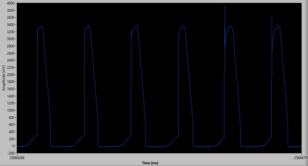
The software used to model the generator was LabVIEW in conjunction with the myRIO. LabVIEW is a graphical programming software and the myRIO is a data acquisition device that has a FPGA and a real-time processor. The myRIO samples two analogue inputs, the sensing voltage and the AVR field voltage. The myRIO monitors the sensing voltage and feeds the AVR field voltage through a transfer function, the generator model, and then feeds the output to the amplifier. The Human Machine Interface is displayed on the host computer, which has some user inputs to vary the parameters of the transfer function and load current in real time.
Figure 3: AVR Output on the HMI
Testing & Results
Closing the loop provided a system that could feed an input into the AVR and then receive, monitor and then respond to that signal. Varying the user input and graphing the signals allowed a comparison between the expected results and the actual results.
Figure 4: Terminal Voltage response after a load disturbance
Project Achievements
- Designed and manufactured a closed loop system that can portably test and analyse the AVR response
- Successfully modeled a generator and used it in simulation
- Built a functional program with a user friendly HMI


