Difference between revisions of "Projects:2014s2-80 Swinging Crane Project"
(→1.1.Technical background) |
(→1.1.Technical background) |
||
| Line 10: | Line 10: | ||
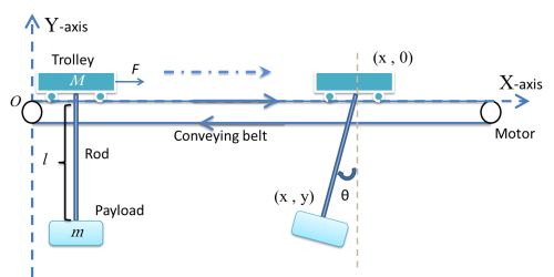
Figure 1 demonstrates the model of swinging crane, the DC motor controls the trolley to horizontally move a load in a short distance. There are two encoders to record the data, one is the moving distance, and another is sway angle of the load. By giving a signal from operation control system, it will generate a DC current from a current source, then injecting it into a motor, which would drive the conveyor belt. There is a trolley placed on one side of the belt, and start moving towards another side. At the bottom of the trolley, using a rod stand for the hoist, connect with a load. At the start of transporting the loads, it will cause accelerated, corresponds to a traction force, effect on the trolley. There occur an angle between the rod and vertical. After the trolley stops, the loads may turn to oscillate. If the initial angle large, the oscillation duration roses, which is a potential risk to the people on the ground. | Figure 1 demonstrates the model of swinging crane, the DC motor controls the trolley to horizontally move a load in a short distance. There are two encoders to record the data, one is the moving distance, and another is sway angle of the load. By giving a signal from operation control system, it will generate a DC current from a current source, then injecting it into a motor, which would drive the conveyor belt. There is a trolley placed on one side of the belt, and start moving towards another side. At the bottom of the trolley, using a rod stand for the hoist, connect with a load. At the start of transporting the loads, it will cause accelerated, corresponds to a traction force, effect on the trolley. There occur an angle between the rod and vertical. After the trolley stops, the loads may turn to oscillate. If the initial angle large, the oscillation duration roses, which is a potential risk to the people on the ground. | ||
| − | [[File:System_structure_flow_chart.png|320px|thumb|left|Figure 2.System structure flow]][[File:Plant_structure_flow_chart.png|320px|thumb| | + | [[File:System_structure_flow_chart.png|320px|thumb|left|Figure 2.System structure flow]][[File:Plant_structure_flow_chart.png|320px|thumb|left|Figure 3.Plant structure flow]] |
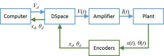
The system is operated inside a flow, shown as Figure 2. Input signal is generated from Simulink, goes into the plant through dSPACE and amplifier. The outputs of the plant are measured by two encoders, and send back to dSPACE, finally transfer to the computer. The dSPACE and amplifier components will introduce later. The plant is the real model of the system, the transfer relationship is shown in Figure 3. The current flows into DC motor, which drives the belt on the grid. The trolley is bind on the belt, thus it has the same acceleration with the belt. There are two outputs from the, the trolley position and the swinging angle of the pendulum. | The system is operated inside a flow, shown as Figure 2. Input signal is generated from Simulink, goes into the plant through dSPACE and amplifier. The outputs of the plant are measured by two encoders, and send back to dSPACE, finally transfer to the computer. The dSPACE and amplifier components will introduce later. The plant is the real model of the system, the transfer relationship is shown in Figure 3. The current flows into DC motor, which drives the belt on the grid. The trolley is bind on the belt, thus it has the same acceleration with the belt. There are two outputs from the, the trolley position and the swinging angle of the pendulum. | ||
Revision as of 12:42, 6 May 2015
Project aim: Swinging Crane project is aim to transporting a payload from one place to another and reducing the consuming time as much as possible.
Contents
1.Project introduction
1.1.Technical background
Gantry cranes are wildly used in industry, for lifting heavy objects by a hoist which is fitted in a hoist trolley and can move horizontally on a rail or pair of rails fitted under a beam.
Figure 1 demonstrates the model of swinging crane, the DC motor controls the trolley to horizontally move a load in a short distance. There are two encoders to record the data, one is the moving distance, and another is sway angle of the load. By giving a signal from operation control system, it will generate a DC current from a current source, then injecting it into a motor, which would drive the conveyor belt. There is a trolley placed on one side of the belt, and start moving towards another side. At the bottom of the trolley, using a rod stand for the hoist, connect with a load. At the start of transporting the loads, it will cause accelerated, corresponds to a traction force, effect on the trolley. There occur an angle between the rod and vertical. After the trolley stops, the loads may turn to oscillate. If the initial angle large, the oscillation duration roses, which is a potential risk to the people on the ground.
The system is operated inside a flow, shown as Figure 2. Input signal is generated from Simulink, goes into the plant through dSPACE and amplifier. The outputs of the plant are measured by two encoders, and send back to dSPACE, finally transfer to the computer. The dSPACE and amplifier components will introduce later. The plant is the real model of the system, the transfer relationship is shown in Figure 3. The current flows into DC motor, which drives the belt on the grid. The trolley is bind on the belt, thus it has the same acceleration with the belt. There are two outputs from the, the trolley position and the swinging angle of the pendulum.
2.Background
3.Previous work
4.Model designing
5.Control methods designing
6.Hardware test and interfacing
7.Results comparison
8.Conclusion
9.Group members
Liyan Yi
Xianghui Ma
10.Supervisors
Dr.Wen Soong [1]
Dr Braden Phillips [2]


