Difference between revisions of "Projects:2018s1-182 Inertia Characterisation and Modelling in a Renewable Energy and Battery Based Microgrid"
(→Objectives) |
(→Project Results) |
||
| (37 intermediate revisions by 2 users not shown) | |||
| Line 1: | Line 1: | ||
= Introduction = | = Introduction = | ||
| − | Synchronous inertia, is basically the amount of stored energy in a power system that can be utilised during supply demand imbalances. Recently, due to high penetration of | + | Synchronous inertia, is basically the amount of stored energy in a power system that can be utilised during supply demand imbalances. Recently, due to high penetration of wind and solar power in a power system, this form of inertia has slowly been decreasing thus causing instability in the power system as the frequency fluctuates more. |
| − | A possible solution for this is | + | A possible solution for this is to provide more stored energy in the system using batteries. This is called synthetic inertia. Although not instantaneous like synchronous inertia, with fast frequency processing, synthetic inertia could be a viable way of minimising supply demand imbalances at all times and therefore stabilising frequency. |
== Project Team == | == Project Team == | ||
| Line 9: | Line 9: | ||
:* Pei Ying Lim | :* Pei Ying Lim | ||
| − | == Project | + | == Project Supervisors == |
| Line 15: | Line 15: | ||
:* Dr Wai-Kin Wong (Electranet) | :* Dr Wai-Kin Wong (Electranet) | ||
| + | = Motivation = | ||
| − | + | :Power system are changing rapidly across the world. In South Australia, approximately 50% of the electricity is produced by asynchronous generator. However, asynchronous generation does not provided any inertia as the traditional synchronous generation. | |
| − | Power | + | [[File:PowerSwing.png]] |
| + | :From the equation above, we can see if there is a step load injected, the rate of change of frequency (RoCoF) will increase significantly if the amount of inertia low. This is cause a frequency drop, and hence power system instability. For example, the event of South Australia blackout on September 2016 is due to low system inertia. | ||
| + | :A solution to this is to use more stored energy such as batteries to provide synthetic inertia together with fast frequency response. | ||
| − | + | = Objectives = | |
| − | + | The objective of this project is to model a renewable energy and battery based microgrid focusing on inertia characterisation. The project objectives are listed below : | |
| − | + | : a) Develop microgrid with +/- 0.15Hz of frequency regulation | |
| − | a) Develop microgrid with +/- 0.15Hz of frequency regulation | + | : b) Improve the rate of change of frequency measurement (RoCoF) scheme |
| − | b) Improve the rate of change of frequency measurement (RoCoF) scheme | + | : c) Demonstrate the role of battery energy storage solution (BESS) for frequency regulation and frequency contingency |
| − | c) Demonstrate the role of battery energy storage solution (BESS) for frequency regulation and frequency contingency | + | : d) Software modelling and validation |
| − | d) Software modelling and | ||
| − | = Project | + | = Project Structure = |
This project is divided into multiple stages. | This project is divided into multiple stages. | ||
| − | Stage 1 : | + | : Stage 0 - Literature Research |
| + | : Stage 1 - Validation of Previous Result | ||
| + | : Stage 2 - New System Improvements | ||
| + | : Stage 3 - Software Modelling and Validation | ||
| + | |||
| + | = Project Stages = | ||
| + | |||
| + | Stage 1 - Validation of Previous Results. | ||
| + | : In this stage, we reproduced the setup from the previous year and aimed to validate previous results. | ||
| + | : | ||
| + | : We repeated all the experimental test beds that were performed in 2017. However, the exact results were not recreated because of the petrol generator itself. There were a number of problems with the generator, these included a fluctuating output voltage frequency and a distorted voltage sine wave. Under the load step changes that were imposed on the generator in these test beds, these problems were amplified. After reproducing the previous results to an acceptable limit, a deeper understanding of this system and its problems was realised allowing a platform for the remainder of the project to commence from. | ||
| + | |||
| + | Stage 2 - The New System | ||
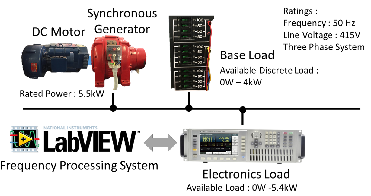
| + | : Due to the problems with the petrol generator it was replaced with a different system incorporating a DC Motor as the prime mover of a three phase synchronous generator. Simple resistive loads were applied to the system under operation to act as the "base load", electronic load banks were attached to each phase and were controlled by LabVIEW software. The same test beds were applied to this system to investigate the difference, the results showing that the new setup was superior. Following this, the LabVIEW software was significantly adjusted such that it could measure a declining frequency and turn the E-Loads off accordingly (FFR). It is important to note that this fast frequency response action was implemented such that it was controlled by the frequency and was basically blind as too what the electronic loads were doing. Once this was implemented, various scenarios were tested and the characteristics of this FFR and this system as a whole were recorded. | ||
| + | [[File:NewSetup.png]] | ||
| + | |||
| + | Stage 3 - Modelling the System | ||
| + | : With a viable system and useful results the system needed to be modelled such that this FFR solution could be scaled and investigated further to prove its use in frequency stability in power systems. The system was modelled initially in Power Factory which is a power systems modelling tool. However, it was difficult to accurately model this system in Power Factory. The difficulty was due to the nature of the inherent frequency control of this system. In this case the DC Motor prime mover's output power is controlled by the frequency and it therefore acts like a governor with a substantial droop. Firstly all the known settings and parameters were modelled but modelling the DC Motor Prime Mover as a Governor was basically trial and error. In some cases the model was similar to the actual system, however it was not accurate enough. | ||
| + | : | ||
| + | : It was then decided to model the system in MATLAB instead as the DC Motor as a Prime Mover could be modelled as it actually is. MATLAB allowed the model to include intricate details of the system including all the load and generation power profiles, the inertia, the DC Motor as a Prime Mover, all the associated delays, etc. The settings and parameters that this model were changed predictably such that the model could be continually adjusted to be an accurate representation of the system. | ||
| + | : | ||
| + | : Once the Model was finalised it could be used to perform simulations of different scenarios and on a larger scale. A model in Power Factory could have been placed in a different model of a complex power system such as the South Australian Power System and the behaviour of FFR could have been investigated on a large scale in a variety of ways. Unfortunately, since the accurate model was created in MATLAB any simulations would need to be quite simple or high level as modelling a complex power system would be infeasible. Nevertheless simple simulations were performed as are discussed below. | ||
= Project Results = | = Project Results = | ||
| + | Stage 1 - Validation of Previous Results. | ||
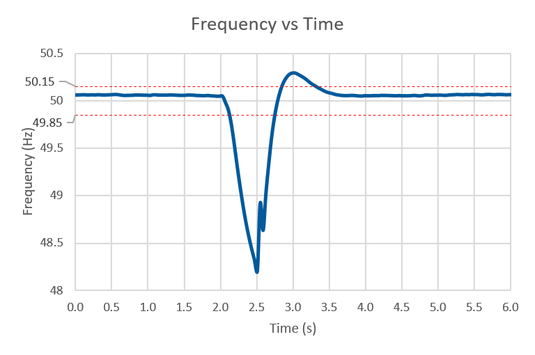
| + | : We have reproduced the previous setup. The problem we faced is that the frequency of the petrol generator fluctuates a lot (beyond 0.15Hz), hence a stable frequency response is not achievable from the setup. The results are shown in the figure below. | ||
| + | [[File:Stage_1_Result.PNG]] | ||
| + | |||
| + | Stage 2 - The New System | ||
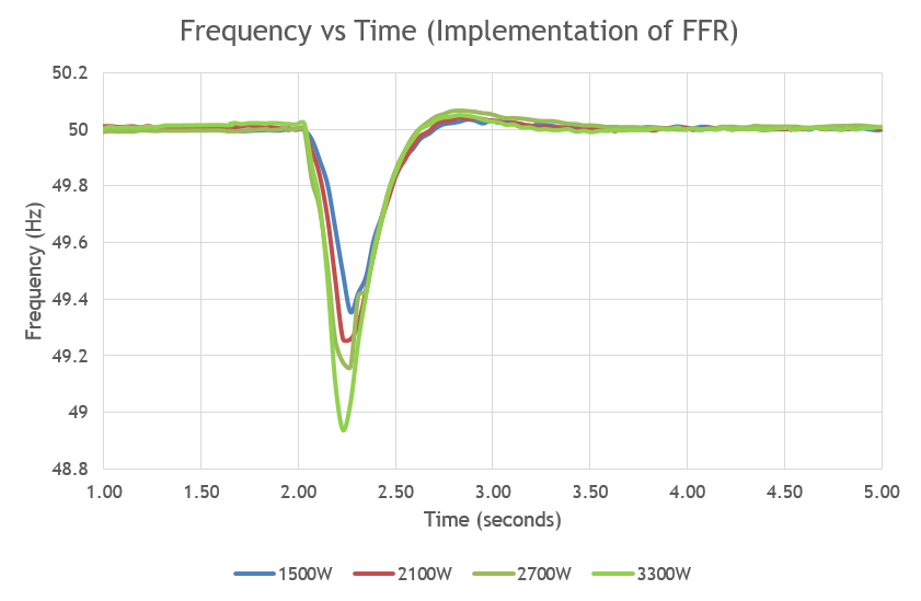
| + | : We implemented the microgrid in the machines lab using a DC Machine to drive the synchronous machine as a generator. The testbed from previous year is repeated in the three phase system. We have +-0.02Hz of frequency variation during regulation, which is one of our objectives. | ||
| + | [[File:Stage 2 Result.png]] | ||
| + | |||
| + | : We then implemented the Fast Frequency Response System in LabVIEW and the electronic loads will turn on at 2 seconds and turn off when the frequency is detected to be 49.9Hz. The delay of the system is 160ms. After testing the frequency processing system, the delay in LabVIEW is 21ms, all the other delays are from the communication between the electronic loads, LabVIEW software and the hardware data acquisition. Hence, we decided not to change the frequency processing software as this would require a whole new system setup. | ||
| + | :The load injected to the system ranges from 1500W to 3300W. As the power injected increases, the frequency dip increases, rate of change of frequency increases as well, provided with the same amount of inertia. The starting frequency and the settling frequency of the system is equal to 50Hz which indicates that the system is stable. | ||
| + | [[File:Stage 3 Result.png]] | ||
| + | |||
| + | Stage 3 - Modelling the System | ||
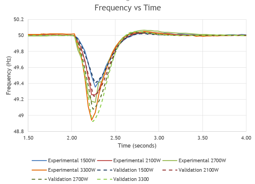
| + | : We have implemented our system model in MATLAB as described above. The graph shown below is a comparison between the model and the system itself under different operating conditions. The frequency dip as well as the overshoot are all within 0.05Hz of error indicating the validity of this model. | ||
| + | [[File:Stage_4_Result.PNG]] | ||
| + | |||
| + | : The model was then extended to perform a simulation of the South Australian Black System in 2016. While the simulation is a large simplification of this event the critical conditions of the event have been more accurately recreated, such as the ROCOF and the conditions of the magnitudes of the generators and the loads. The simulation shows the possible outcomes had different magnitudes of FFR been applied to this system during the event. The controller for this FFR was exactly the same as the model we created, the FFR was just different in magnitude. | ||
| + | [[File:Simulation.png]] | ||
| + | : As can be seen in the above figure, different magnitudes of FFR would have different effects on the system. It is possible, referring to the above graph, that if 200MW FFR was applied to this system using the same control system that was used in our system, then the Black System may not have occurred and the grid would have stabilized. | ||
= Project Conclusions and Further Studies = | = Project Conclusions and Further Studies = | ||
| + | :Through out this project, we have : | ||
| + | ::Development of a stable three phase microgrid hardware experimental testbed to represent the real world | ||
| + | ::A stable frequency response with ±0.02Hz of frequency regulation. | ||
| + | ::Development of a fast frequency response system in LabView | ||
| + | ::Development and validation in Matlab | ||
| + | :Power system with battery storage and fast frequency response system could produce synthetic inertia and reduce the rate of change of frequency which could increase the stability of the system. | ||
| + | :The future project could improve the frequency processing technique improve the model such that it models the SA or any other grid. | ||
= References = | = References = | ||
| − | [1] | + | : [1]Deloitte, “Energy markets and the implications of renewables,” Deloitte, Adelaide, 2015. |
| − | Deloitte, “Energy markets and the implications of renewables,” Deloitte, Adelaide, 2015. | + | : [2] M. A. Pelletier, M. E. Phethean and S. Nutt, “Grid code requirements for artificial inertia control systems in the New Zealand Power System,” Transpower, Wellington, 2012. |
| − | [2] | + | : [3] A. Portelli, “Inertia Characterisation and Modelling in a Renewable Energy and Battery Based Microgrid,” The University of Adelaide, Adelaide, 2017. |
| − | M. A. Pelletier, M. E. Phethean and S. Nutt, “Grid code requirements for artificial inertia control systems in the New Zealand Power System,” Transpower, Wellington, 2012. | + | : [4] R. Eriksson, N. Modig and K. Elkington, “Synthetic inertia versus fast frequency,” IET Journals, Sundbyberg, 2017. |
| − | [3] | + | : [5] H. Thiesen, C. Jauch and A. Gloe, “Design of a System Substituting Today’s Inherent Inertia in the European Continental Synchronous Area,” Hochschule Flensburg, Flensburg, 2016. |
| − | A. Portelli, “Inertia Characterisation and Modelling in a Renewable Energy and Battery Based Microgrid,” The University of Adelaide, Adelaide, 2017. | + | : [6] N. Miller, “Technology Capabilities for Fast Frequency Response,” General Electric, Schenectady, New York, 2017. |
| − | [4] | + | : [7] M. B. S. M. Seyedi, “The Utilization of Synthetic Inertia From Wind Farms And Its Impact On Existing Speed Governors And System Performance,” Elforsk AB, Stockholm, 2013. |
| − | R. Eriksson, N. Modig and K. Elkington, “Synthetic inertia versus fast frequency,” IET Journals, Sundbyberg, 2017. | + | : [8] F. G. -. Longatt, “IMPACT OF SYNTHETIC INERTIA FROM WIND POWER ON THE PROTECTION/CONTROL SCHEMES OF FUTURE POWER SYSTEMS: SIMULATION STUDY,” Faculty of Computering and Engineering, Coventry University, Coventry, 2012. |
| − | [5] | + | : [9] C. T. Nguyen and K. Srinivasan, “A New Technique for Rapid Tracking of Frequency Deviations Based on Level Crossings,” IEEE, Quebec, 1984. |
| − | H. Thiesen, C. Jauch and A. Gloe, “Design of a System Substituting Today’s Inherent Inertia in the European Continental Synchronous Area,” Hochschule Flensburg, Flensburg, 2016. | + | : [10] G. G. Haines, AESKB Software PMU Analyser V0.1 GH 2017-11-01, Adelaide: The University of Adelaide, 2017. |
| − | [6] | + | : [11] K. Kikkert, “Response from Nesimi Team,” Google, Adelaide, 2018. |
| − | N. Miller, “Technology Capabilities for Fast Frequency Response,” General Electric, Schenectady, New York, 2017. | + | : [12] D. Vowles, Power Systems Lecture Notes, Adelaide: The University of Adelaide, 2017. |
| − | [7] | + | : [13] AEMC, The Frequency Operating Standard, Sydney: AEMC, 2017. |
| − | M. B. S. M. Seyedi, “The Utilization of Synthetic Inertia From Wind Farms And Its Impact On Existing Speed Governors And System Performance,” Elforsk AB, Stockholm, 2013. | + | : [14] “Multi-cylinder Engines (Automobile),” what-when-how, [Online]. Available: http://what-when-how.com/automobile/multi-cylinder-engines-automobile/. |
| − | [8] | + | : [15] E. Explained, Flywheel - Explained, 2012. |
| − | F. G. -. Longatt, “IMPACT OF SYNTHETIC INERTIA FROM WIND POWER ON THE PROTECTION/CONTROL SCHEMES OF FUTURE POWER SYSTEMS: SIMULATION STUDY,” Faculty of Computering and Engineering, Coventry University, Coventry, 2012. | + | : [16] I. Toshio, H. Taniguchi, Y. Ikeguchi and K. Yoshida, Estimation of Power System Inertia Constant and Capacity of Spinning-reserve support Generators Using Measured Frequency Transients, Tokyo; Osaka: IEEE, 1997. |
| − | [9] | ||
| − | C. T. Nguyen and K. Srinivasan, “A New Technique for Rapid Tracking of Frequency Deviations Based on Level Crossings,” IEEE, Quebec, 1984. | ||
| − | [10] | ||
| − | G. G. Haines, AESKB Software PMU Analyser V0.1 GH 2017-11-01, Adelaide: The University of Adelaide, 2017. | ||
| − | [11] | ||
| − | K. Kikkert, “Response from Nesimi Team,” Google, Adelaide, 2018. | ||
| − | [12] | ||
| − | D. Vowles, Power Systems Lecture Notes, Adelaide: The University of Adelaide, 2017. | ||
| − | [13] | ||
| − | AEMC, The Frequency Operating Standard, Sydney: AEMC, 2017. | ||
| − | [14] | ||
| − | “Multi-cylinder Engines (Automobile),” what-when-how, [Online]. Available: http://what-when-how.com/automobile/multi-cylinder-engines-automobile/ | ||
| − | [15] | ||
| − | E. Explained, Flywheel - Explained, 2012. | ||
| − | [16] | ||
| − | I. Toshio, H. Taniguchi, Y. Ikeguchi and K. Yoshida, Estimation of Power System Inertia Constant and Capacity of Spinning-reserve support Generators Using Measured Frequency Transients, Tokyo; Osaka: IEEE, 1997. | ||
Latest revision as of 14:54, 19 October 2018
Contents
Introduction
Synchronous inertia, is basically the amount of stored energy in a power system that can be utilised during supply demand imbalances. Recently, due to high penetration of wind and solar power in a power system, this form of inertia has slowly been decreasing thus causing instability in the power system as the frequency fluctuates more.
A possible solution for this is to provide more stored energy in the system using batteries. This is called synthetic inertia. Although not instantaneous like synchronous inertia, with fast frequency processing, synthetic inertia could be a viable way of minimising supply demand imbalances at all times and therefore stabilising frequency.
Project Team
- Maxwell Weppner
- Pei Ying Lim
Project Supervisors
- Assoc Prof. Nesimi Ertugrul
- Dr Wai-Kin Wong (Electranet)
Motivation
- Power system are changing rapidly across the world. In South Australia, approximately 50% of the electricity is produced by asynchronous generator. However, asynchronous generation does not provided any inertia as the traditional synchronous generation.
- From the equation above, we can see if there is a step load injected, the rate of change of frequency (RoCoF) will increase significantly if the amount of inertia low. This is cause a frequency drop, and hence power system instability. For example, the event of South Australia blackout on September 2016 is due to low system inertia.
- A solution to this is to use more stored energy such as batteries to provide synthetic inertia together with fast frequency response.
Objectives
The objective of this project is to model a renewable energy and battery based microgrid focusing on inertia characterisation. The project objectives are listed below :
- a) Develop microgrid with +/- 0.15Hz of frequency regulation
- b) Improve the rate of change of frequency measurement (RoCoF) scheme
- c) Demonstrate the role of battery energy storage solution (BESS) for frequency regulation and frequency contingency
- d) Software modelling and validation
Project Structure
This project is divided into multiple stages.
- Stage 0 - Literature Research
- Stage 1 - Validation of Previous Result
- Stage 2 - New System Improvements
- Stage 3 - Software Modelling and Validation
Project Stages
Stage 1 - Validation of Previous Results.
- In this stage, we reproduced the setup from the previous year and aimed to validate previous results.
- We repeated all the experimental test beds that were performed in 2017. However, the exact results were not recreated because of the petrol generator itself. There were a number of problems with the generator, these included a fluctuating output voltage frequency and a distorted voltage sine wave. Under the load step changes that were imposed on the generator in these test beds, these problems were amplified. After reproducing the previous results to an acceptable limit, a deeper understanding of this system and its problems was realised allowing a platform for the remainder of the project to commence from.
Stage 2 - The New System
- Due to the problems with the petrol generator it was replaced with a different system incorporating a DC Motor as the prime mover of a three phase synchronous generator. Simple resistive loads were applied to the system under operation to act as the "base load", electronic load banks were attached to each phase and were controlled by LabVIEW software. The same test beds were applied to this system to investigate the difference, the results showing that the new setup was superior. Following this, the LabVIEW software was significantly adjusted such that it could measure a declining frequency and turn the E-Loads off accordingly (FFR). It is important to note that this fast frequency response action was implemented such that it was controlled by the frequency and was basically blind as too what the electronic loads were doing. Once this was implemented, various scenarios were tested and the characteristics of this FFR and this system as a whole were recorded.
Stage 3 - Modelling the System
- With a viable system and useful results the system needed to be modelled such that this FFR solution could be scaled and investigated further to prove its use in frequency stability in power systems. The system was modelled initially in Power Factory which is a power systems modelling tool. However, it was difficult to accurately model this system in Power Factory. The difficulty was due to the nature of the inherent frequency control of this system. In this case the DC Motor prime mover's output power is controlled by the frequency and it therefore acts like a governor with a substantial droop. Firstly all the known settings and parameters were modelled but modelling the DC Motor Prime Mover as a Governor was basically trial and error. In some cases the model was similar to the actual system, however it was not accurate enough.
- It was then decided to model the system in MATLAB instead as the DC Motor as a Prime Mover could be modelled as it actually is. MATLAB allowed the model to include intricate details of the system including all the load and generation power profiles, the inertia, the DC Motor as a Prime Mover, all the associated delays, etc. The settings and parameters that this model were changed predictably such that the model could be continually adjusted to be an accurate representation of the system.
- Once the Model was finalised it could be used to perform simulations of different scenarios and on a larger scale. A model in Power Factory could have been placed in a different model of a complex power system such as the South Australian Power System and the behaviour of FFR could have been investigated on a large scale in a variety of ways. Unfortunately, since the accurate model was created in MATLAB any simulations would need to be quite simple or high level as modelling a complex power system would be infeasible. Nevertheless simple simulations were performed as are discussed below.
Project Results
Stage 1 - Validation of Previous Results.
- We have reproduced the previous setup. The problem we faced is that the frequency of the petrol generator fluctuates a lot (beyond 0.15Hz), hence a stable frequency response is not achievable from the setup. The results are shown in the figure below.
Stage 2 - The New System
- We implemented the microgrid in the machines lab using a DC Machine to drive the synchronous machine as a generator. The testbed from previous year is repeated in the three phase system. We have +-0.02Hz of frequency variation during regulation, which is one of our objectives.
- We then implemented the Fast Frequency Response System in LabVIEW and the electronic loads will turn on at 2 seconds and turn off when the frequency is detected to be 49.9Hz. The delay of the system is 160ms. After testing the frequency processing system, the delay in LabVIEW is 21ms, all the other delays are from the communication between the electronic loads, LabVIEW software and the hardware data acquisition. Hence, we decided not to change the frequency processing software as this would require a whole new system setup.
- The load injected to the system ranges from 1500W to 3300W. As the power injected increases, the frequency dip increases, rate of change of frequency increases as well, provided with the same amount of inertia. The starting frequency and the settling frequency of the system is equal to 50Hz which indicates that the system is stable.
Stage 3 - Modelling the System
- We have implemented our system model in MATLAB as described above. The graph shown below is a comparison between the model and the system itself under different operating conditions. The frequency dip as well as the overshoot are all within 0.05Hz of error indicating the validity of this model.
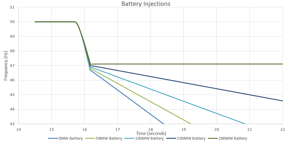
- The model was then extended to perform a simulation of the South Australian Black System in 2016. While the simulation is a large simplification of this event the critical conditions of the event have been more accurately recreated, such as the ROCOF and the conditions of the magnitudes of the generators and the loads. The simulation shows the possible outcomes had different magnitudes of FFR been applied to this system during the event. The controller for this FFR was exactly the same as the model we created, the FFR was just different in magnitude.
- As can be seen in the above figure, different magnitudes of FFR would have different effects on the system. It is possible, referring to the above graph, that if 200MW FFR was applied to this system using the same control system that was used in our system, then the Black System may not have occurred and the grid would have stabilized.
Project Conclusions and Further Studies
- Through out this project, we have :
- Development of a stable three phase microgrid hardware experimental testbed to represent the real world
- A stable frequency response with ±0.02Hz of frequency regulation.
- Development of a fast frequency response system in LabView
- Development and validation in Matlab
- Power system with battery storage and fast frequency response system could produce synthetic inertia and reduce the rate of change of frequency which could increase the stability of the system.
- The future project could improve the frequency processing technique improve the model such that it models the SA or any other grid.
References
- [1]Deloitte, “Energy markets and the implications of renewables,” Deloitte, Adelaide, 2015.
- [2] M. A. Pelletier, M. E. Phethean and S. Nutt, “Grid code requirements for artificial inertia control systems in the New Zealand Power System,” Transpower, Wellington, 2012.
- [3] A. Portelli, “Inertia Characterisation and Modelling in a Renewable Energy and Battery Based Microgrid,” The University of Adelaide, Adelaide, 2017.
- [4] R. Eriksson, N. Modig and K. Elkington, “Synthetic inertia versus fast frequency,” IET Journals, Sundbyberg, 2017.
- [5] H. Thiesen, C. Jauch and A. Gloe, “Design of a System Substituting Today’s Inherent Inertia in the European Continental Synchronous Area,” Hochschule Flensburg, Flensburg, 2016.
- [6] N. Miller, “Technology Capabilities for Fast Frequency Response,” General Electric, Schenectady, New York, 2017.
- [7] M. B. S. M. Seyedi, “The Utilization of Synthetic Inertia From Wind Farms And Its Impact On Existing Speed Governors And System Performance,” Elforsk AB, Stockholm, 2013.
- [8] F. G. -. Longatt, “IMPACT OF SYNTHETIC INERTIA FROM WIND POWER ON THE PROTECTION/CONTROL SCHEMES OF FUTURE POWER SYSTEMS: SIMULATION STUDY,” Faculty of Computering and Engineering, Coventry University, Coventry, 2012.
- [9] C. T. Nguyen and K. Srinivasan, “A New Technique for Rapid Tracking of Frequency Deviations Based on Level Crossings,” IEEE, Quebec, 1984.
- [10] G. G. Haines, AESKB Software PMU Analyser V0.1 GH 2017-11-01, Adelaide: The University of Adelaide, 2017.
- [11] K. Kikkert, “Response from Nesimi Team,” Google, Adelaide, 2018.
- [12] D. Vowles, Power Systems Lecture Notes, Adelaide: The University of Adelaide, 2017.
- [13] AEMC, The Frequency Operating Standard, Sydney: AEMC, 2017.
- [14] “Multi-cylinder Engines (Automobile),” what-when-how, [Online]. Available: http://what-when-how.com/automobile/multi-cylinder-engines-automobile/.
- [15] E. Explained, Flywheel - Explained, 2012.
- [16] I. Toshio, H. Taniguchi, Y. Ikeguchi and K. Yoshida, Estimation of Power System Inertia Constant and Capacity of Spinning-reserve support Generators Using Measured Frequency Transients, Tokyo; Osaka: IEEE, 1997.

