Difference between revisions of "Projects:2014S1-43 Inverter Drive Experiment"
(→Project Description) |
|||
| (5 intermediate revisions by the same user not shown) | |||
| Line 1: | Line 1: | ||
| − | + | = Project Aims = | |
1. A student experiment will be developed to show the principles and operation of the inverter drive system. | 1. A student experiment will be developed to show the principles and operation of the inverter drive system. | ||
| Line 7: | Line 7: | ||
3. Test the inverter drive system until all devices are able to work properly, hence use inverter to change the working conditions of induction motor as well as collect useful data. | 3. Test the inverter drive system until all devices are able to work properly, hence use inverter to change the working conditions of induction motor as well as collect useful data. | ||
| − | + | = Background = | |
The electrical engineering faculty of the University of Adelaide has recently received funding to purchase ten variable-speed inverter drives (Motiflex e100). Moreover, EEE students have learnt the knowledge of induction machines in the 3rd year course Electric Energy Systems and have studied basic theories about inverter in Power Electronic and Motor Drive. As a result, the faculty plan to develop a variable-speed induction machine experiment to let the student have a better comprehension about inverter drives. | The electrical engineering faculty of the University of Adelaide has recently received funding to purchase ten variable-speed inverter drives (Motiflex e100). Moreover, EEE students have learnt the knowledge of induction machines in the 3rd year course Electric Energy Systems and have studied basic theories about inverter in Power Electronic and Motor Drive. As a result, the faculty plan to develop a variable-speed induction machine experiment to let the student have a better comprehension about inverter drives. | ||
| − | + | = Project Description = | |
| − | + | == Hardware == | |
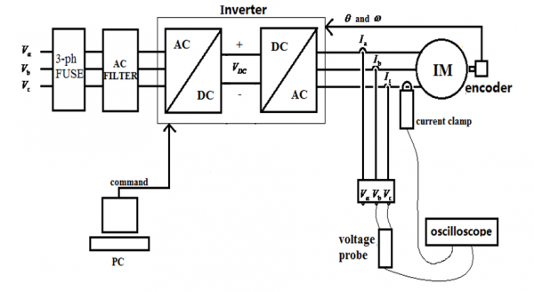
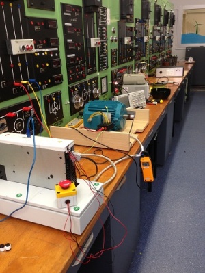
| − | + | Install one inerter drive system in the laboratory and ensure all devices working in the system are able to work properly. The working output of the system, the induction motor, is controlled by inverter. The devices include the inverter Motiflex e100, a four-pole induction motor, AC supply (240V 50HZ), fuses, AC filter, encoder, voltage and current sensor, oscilloscope and computers.The pictures below show the system layout and overview. | |
| − | + | [[File:block diagram.png|600px|]] | |
| − | [[File: | + | [[File:o1.jpg|300px|]] |
| − | + | == Software == | |
| + | Designing an interface based on the Mint WorkBench software in order to control the inverter by different programs and hence drive the induction motor. | ||
| − | == Group Members | + | [[File:MINT.png|600px|]] |
| + | |||
| + | |||
| + | == Experiment sheet == | ||
| + | A student experiment sheet will be developed to demonstrate the principles and operation of the inverter drive system. The specific operating steps as well as working diagram will show in the experiment sheet. In addition, report questions and sample answers are included. | ||
| + | |||
| + | == Data analysis == | ||
| + | Under different switching frequenies and motor velocities, voltage and current curves captured by oscilloscope could be use to analyze. Both Volts-Per-Hertz Control and Vector Control are involved. The picture below shows Vector Control is more precisely with less vibration. | ||
| + | |||
| + | [[File:compare.png|500px|]] | ||
| + | |||
| + | = Group Members = | ||
Wanshu Guo | Wanshu Guo | ||
| Line 26: | Line 38: | ||
Cheng Yue Yang | Cheng Yue Yang | ||
| − | + | = Supervisors = | |
Dr Wen Soong | Dr Wen Soong | ||
Dr Ertugrul Nesimi | Dr Ertugrul Nesimi | ||
Latest revision as of 12:19, 25 October 2014
Contents
Project Aims
1. A student experiment will be developed to show the principles and operation of the inverter drive system.
2. Design and install an inverter drive system which includes both hardware and software. The inverter Motiflex e100 is the most important part in this experiment.
3. Test the inverter drive system until all devices are able to work properly, hence use inverter to change the working conditions of induction motor as well as collect useful data.
Background
The electrical engineering faculty of the University of Adelaide has recently received funding to purchase ten variable-speed inverter drives (Motiflex e100). Moreover, EEE students have learnt the knowledge of induction machines in the 3rd year course Electric Energy Systems and have studied basic theories about inverter in Power Electronic and Motor Drive. As a result, the faculty plan to develop a variable-speed induction machine experiment to let the student have a better comprehension about inverter drives.
Project Description
Hardware
Install one inerter drive system in the laboratory and ensure all devices working in the system are able to work properly. The working output of the system, the induction motor, is controlled by inverter. The devices include the inverter Motiflex e100, a four-pole induction motor, AC supply (240V 50HZ), fuses, AC filter, encoder, voltage and current sensor, oscilloscope and computers.The pictures below show the system layout and overview.
Software
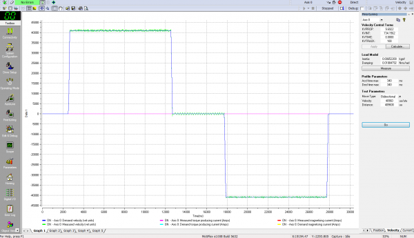
Designing an interface based on the Mint WorkBench software in order to control the inverter by different programs and hence drive the induction motor.
Experiment sheet
A student experiment sheet will be developed to demonstrate the principles and operation of the inverter drive system. The specific operating steps as well as working diagram will show in the experiment sheet. In addition, report questions and sample answers are included.
Data analysis
Under different switching frequenies and motor velocities, voltage and current curves captured by oscilloscope could be use to analyze. Both Volts-Per-Hertz Control and Vector Control are involved. The picture below shows Vector Control is more precisely with less vibration.
Group Members
Wanshu Guo
Xiaochuan Li
Cheng Yue Yang
Supervisors
Dr Wen Soong
Dr Ertugrul Nesimi


