Difference between revisions of "Projects:2019s1-119 360˚ Camera Dolly/Rig"
(→Prototype) |
(→Conclusion) |
||
| (7 intermediate revisions by the same user not shown) | |||
| Line 3: | Line 3: | ||
'''Project members''' | '''Project members''' | ||
| − | + | * Chai Chang Zing | |
| − | + | * Silin Wang | |
| − | + | * Zeyu Zhang | |
| − | + | * Yuhao Zhang | |
'''Supervisors''' | '''Supervisors''' | ||
| − | + | * Dr Said al-Sarawi | |
| − | + | * Dr Hong Gunn Chew | |
'''Project Sponsors''' | '''Project Sponsors''' | ||
Adelaide Nursing School | Adelaide Nursing School | ||
| − | + | * Dr Paul McLiesh | |
| − | + | * Mr Christopher Kastelein | |
== Background == | == Background == | ||
| Line 53: | Line 53: | ||
== Methods == | == Methods == | ||
=== Wireless Control === | === Wireless Control === | ||
| − | + | * Using Radio Signal Wave (RC) to control the 360 camera dolly | |
| − | + | * 2.4 GHz | |
| − | + | * RC controller and receiver | |
| − | The RC controller transmit signal pulses and the Micro-controller receive and process the signal pulses. | + | The RC controller transmit signal pulses and the Micro-controller receive and process the signal pulses. |
=== Movement Control === | === Movement Control === | ||
| Line 87: | Line 87: | ||
# Arduino MKR 1000 | # Arduino MKR 1000 | ||
| + | === Internet of Things (IoT) === | ||
| + | Use the Arduino IoT (MKR1000) to display the status of 360 camera dolly which include speed, direction, distance and height of telescope mast. | ||
| + | == Prototype == | ||
| + | === Hardware === | ||
| + | [[File:Poster_hardware_13.jpg|frame|center]] [[File:PCBSEN.png|frame|center]] | ||
| + | |||
| + | === Movement Control System === | ||
| + | [[File:Mecanum wheel.png|frame|center]] | ||
| + | |||
| + | *Three channel used to control movement of dolly | ||
| + | *Each channel control two motion of DC motors | ||
| + | *The speed varies according to how much the joystick is pushed | ||
| + | *Movement control will be interrupt by the collision avoidance system | ||
| + | |||
| + | [[File:Flow.jpg|frame|center]] | ||
| + | |||
| + | |||
| + | === Collision Avoidance System === | ||
| + | [[File:Flow of CAS.png|frame|center]] | ||
| + | [[File:Cover of sensors.jpg|frame|center]] | ||
| + | |||
| + | *Detecting angle of a sensor ~ 30° | ||
| + | *In order to achieve 360-degree detection, 14 sensors were used | ||
| + | |||
| + | === Speed control of Collision avoidance system === | ||
| + | [[File:SPEEDaaa.png|frame|center]] | ||
| − | + | *Maximum Speed : 0.945 m/s | |
| + | *Minimum Speed: 0.261 m/s | ||
| + | *The dolly starts to decelerate when the detected distance is smaller than 1 meter. | ||
| + | *It will reach the minimum speed when the obstacle is 0.1 meter away from the dolly. | ||
| − | == | + | === Electric Telescopic Mast === |
| + | *Using the pulse width signal to control the A4988 driver board to control the stepper motor rotate anticlockwise or clockwise. | ||
| + | *Stepper motor mounted with a spool that can release or collect rope. | ||
| + | *Using pulley system to implement the mast go up and down. | ||
| − | + | [[File:Mast aa.png|frame|center]] | |
| + | == Final Product == | ||
| + | [[File:Final product20191014.jpg|800px|frameless|center]] | ||
| − | == Conclusion == | + | == Conclusion and future work == |
| + | '''Optimize the Collision Avoidance System''' | ||
| + | *Using better ultrasonic sensors | ||
| + | *Decrease the number of sensors and optimize the algorithm | ||
| + | '''Autonomous Robotic System''' | ||
| + | *Implement path finding function of the dolly | ||
| + | *Implement self-return function of the dolly | ||
| + | *Real-time feedback for height of telescopic mast and speed | ||
| + | '''Improve the stability of camera dolly''' | ||
| + | *Shock Absorption | ||
| + | *Suspension of the dolly | ||
== References == | == References == | ||
Latest revision as of 19:55, 29 October 2019
Contents
Project team
Project members
- Chai Chang Zing
- Silin Wang
- Zeyu Zhang
- Yuhao Zhang
Supervisors
- Dr Said al-Sarawi
- Dr Hong Gunn Chew
Project Sponsors Adelaide Nursing School
- Dr Paul McLiesh
- Mr Christopher Kastelein
Background
Aim
To build a remotely controlled dolly/rig that can carry 360 camera and gimbal at varying heights.
Motivation
Allow students to use specific VR headsets to see the video from their perspective without seeing someone carrying the camera by hand.
Requirements
- Remotely controlled from a range
- Rotate on spot
- Accommodate a range of terrain types at variable speeds (walking speed)
- Accommodate variable height settings or mounted camera (0.8m-1.8m)
- Size of the device should limit outside the view of the device from the camera
- Easily transported and operated by a layperson
- Safety for people to use
Methods
Wireless Control
- Using Radio Signal Wave (RC) to control the 360 camera dolly
- 2.4 GHz
- RC controller and receiver
The RC controller transmit signal pulses and the Micro-controller receive and process the signal pulses.
Movement Control
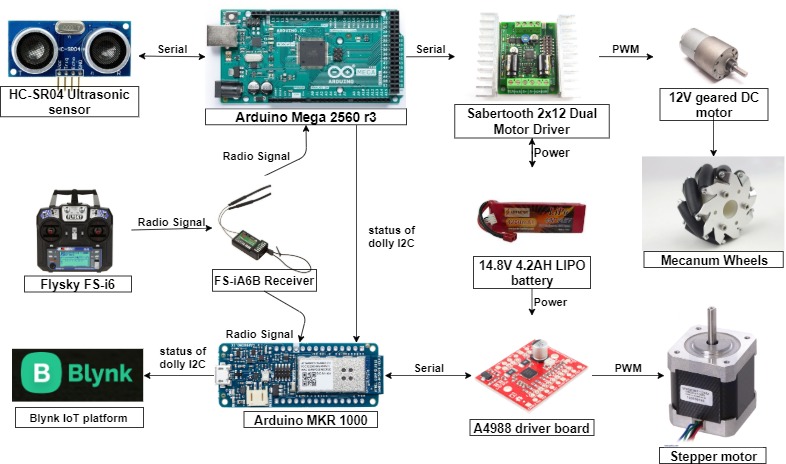
- 4 x 50:1 12V geared DC motor
- 2 x Sabertooth 2x12 dual regenerative motor driver
- Arduino Mega 2560 r3 - Micro-controller
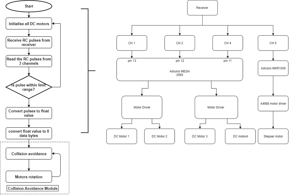
There are 6 available modes in the Sabertooth motor driver. Packet-serial mode is selected to control the DC motors. The RF signal pulses received is converted into float value and then to bytes ranging from -127 to 127. The bytes from 0 to 127 indicates the speed of rotation of a motor while the positive and negative sign of the bytes indicates the direction of the rotation.
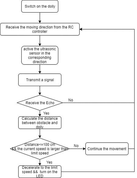
Collision Avoidance System
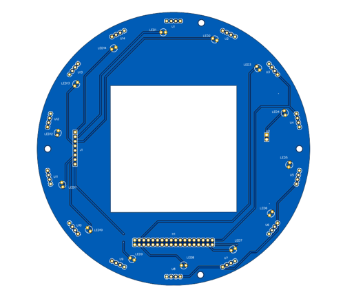
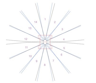
- Ultrasonic sensors - HC-SR04
- 14 Ultrasonic sensors for 360-degree coverage
- Each sensor can detect an object from 0.2 m to 4 m
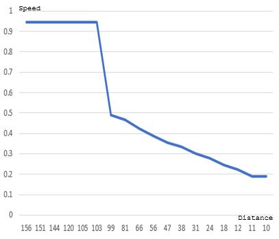
The ultrasonic sensor can detect the distance of an object by calculating the time taken for an echo pulse from the object. The distance obtained is used in decelerating system of the dolly to reduce the effect of collision between the dolly and the obstacles. The deceleration distance is set at 0.8 m and the maximum speed of the dolly will be reduced according to the detected distance.
Telescopic Mast
- RC or Wi-Fi control
- Adjustable height from 0.8 m to 1.8 m
- 12V Stepper motor
- A4988 motor driver
- Arduino MKR 1000
Internet of Things (IoT)
Use the Arduino IoT (MKR1000) to display the status of 360 camera dolly which include speed, direction, distance and height of telescope mast.
Prototype
Hardware
Movement Control System
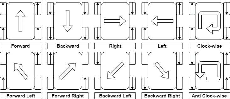
- Three channel used to control movement of dolly
- Each channel control two motion of DC motors
- The speed varies according to how much the joystick is pushed
- Movement control will be interrupt by the collision avoidance system
Collision Avoidance System
- Detecting angle of a sensor ~ 30°
- In order to achieve 360-degree detection, 14 sensors were used
Speed control of Collision avoidance system
- Maximum Speed : 0.945 m/s
- Minimum Speed: 0.261 m/s
- The dolly starts to decelerate when the detected distance is smaller than 1 meter.
- It will reach the minimum speed when the obstacle is 0.1 meter away from the dolly.
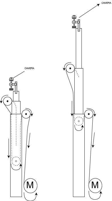
Electric Telescopic Mast
- Using the pulse width signal to control the A4988 driver board to control the stepper motor rotate anticlockwise or clockwise.
- Stepper motor mounted with a spool that can release or collect rope.
- Using pulley system to implement the mast go up and down.
Final Product
Conclusion and future work
Optimize the Collision Avoidance System
- Using better ultrasonic sensors
- Decrease the number of sensors and optimize the algorithm
Autonomous Robotic System
- Implement path finding function of the dolly
- Implement self-return function of the dolly
- Real-time feedback for height of telescopic mast and speed
Improve the stability of camera dolly
- Shock Absorption
- Suspension of the dolly
