Difference between revisions of "Projects:2014S1-06 Bell Ringing Robot: Hawkear"
(→System Component) |
|||
| (3 intermediate revisions by the same user not shown) | |||
| Line 19: | Line 19: | ||
=== System Component === | === System Component === | ||
| − | + | ==== Sensor Box ==== | |
[[File:SensorBoxtest1.jpg]] | [[File:SensorBoxtest1.jpg]] | ||
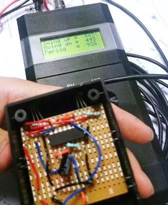
| − | The sensor box consists with a jiffy box (80Lx60Wx30Hmm), a 4-pin male connector and a PCB board with the sensor circuit. | + | *The sensor box consists with a jiffy box (80Lx60Wx30Hmm), a 4-pin male connector and a PCB board with the sensor circuit. |
The sensor box circuit consists with two parts: a monostable circuit and a NAND-gate latch. The Mono-stable circuit is used for Odd Struckness Meter. The NAND-gate latch is used for analyse box and Abel bell ringing simulator. | The sensor box circuit consists with two parts: a monostable circuit and a NAND-gate latch. The Mono-stable circuit is used for Odd Struckness Meter. The NAND-gate latch is used for analyse box and Abel bell ringing simulator. | ||
| − | + | ==== Junction Box ==== | |
[[File:JunctionBox2.jpg]] | [[File:JunctionBox2.jpg]] | ||
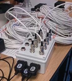
| + | *The Junction Box has four main functions: | ||
| + | 1. Power supply for sensor box (5 V) | ||
| + | 2. Support 12 inputs (12 sensor boxes) | ||
| + | 3. Be able to connect with Abel through three DB9 ports | ||
| + | 4. Be able to connect with Analyse box through a DB25 port | ||
| − | + | ==== Analysis Box ==== | |
[[File:AnalysisBox.jpg]] | [[File:AnalysisBox.jpg]] | ||
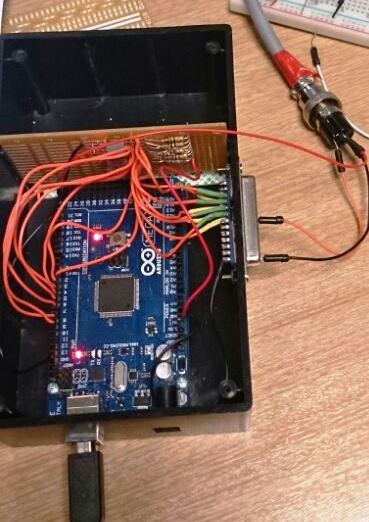
| + | *The main function of the Analyse box is to analyse the data signal from junction box. | ||
| + | The De-bouncing Circuit is used for filtering the noise from long cable. | ||
| + | The analysis box can connect with PC through a USB line. | ||
| + | The analyse box consists with an Arduino mega2560 board inside that have more than 16 digital I/O pin to support up to 16 bells and a Jiffy box (150L×90W×50H). | ||
| + | Mega2560 Arduino board provides enough RAM to store the program and transform the trigger signal. | ||
| + | Because of the near-by mobile base station, there were some noise data in outputs. So the box has been redesigned by added eight de-bouncing circuits to each input signal. | ||
| + | == Data Analysis == | ||
| + | [[File:Data.png]] | ||
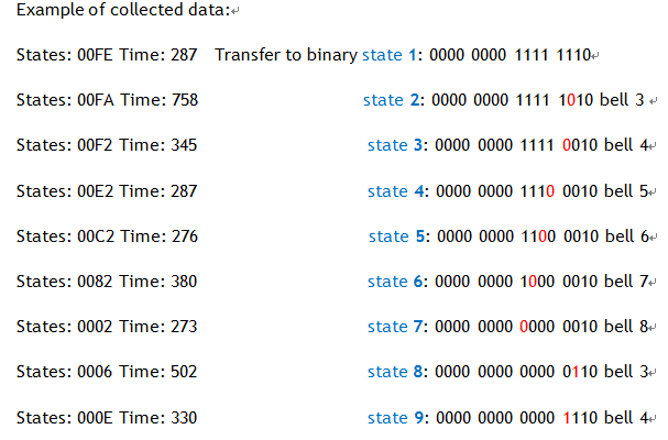
| + | *When read the data, transfer to binary first, for example, state 1 is 0000 0000 1111 1110, state 2 is 0000 0000 1111 1010. Compare to state 1, the third digit (count from right to left) has changed from 1 to 0 (head strike), which means bell number 3 is moving forward. If the digit is changed from 0 to 1 like states 8 to states 9, it means back strike. | ||
| + | |||
| + | [[File:Data1.png]] | ||
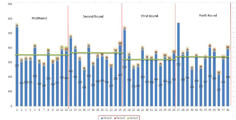
| + | *The green line is average time, calculated by 11 time gaps from order2 to 12 excluding its highest and lowest values. If the time is above the green line over about 50ms means this strike is late, otherwise is head. | ||
== Team == | == Team == | ||
=== Group members === | === Group members === | ||
| Line 35: | Line 52: | ||
=== Supervisors === | === Supervisors === | ||
| − | * Dr | + | * Dr Matthew Sorell |
| − | * Dr | + | * Dr Braden Phillips |
=== Resources === | === Resources === | ||
Latest revision as of 19:57, 29 October 2014
Contents
Project information
Motivation and Background
Change-Ringing has a history of nearly 700 years. It is a highly mathematical collaborative team sport and musical performance. The objective of this project is to work towards a fully autonomous robot which can ring with a team made up of robots and humans to achieve high quality ringing, using audible clues to maintain control of the bells. Hawkear is a new computer system designed to help the judges in bell ringing contests in the same way "Hawkeye" helps as referees. As the first year of this long term project, the main goal is to use Hall effect sensors build a bell striking analysis system which is comparable to David Bagley’s system, should be able to connect with PC interface, the Odd Struckness Meter and detect the strike motion.
Project Aims
The project aims to develop a bell striking analysis system, which is capable of:
- Sensor induction
When the hall sensor is triggered, the sensor box should be able to send the signal through the 12.5-meter cable. The cable can plug into Bagley's Odd Struckness Meter. OSM allows accurate measurements to be made of the swing times of a bell and its clapper. The data can be used to help minimise oddstruckness[1]. The OSM also shows which bells in a ring need adjusting, and by how much it need to be adjusted[1].
- Data acquisition
By connecting the junction box to the Abel interface, the Abel interface can record the data information of each bell. The junction box also can connect with the analysis box, the program in the Aduino board can calculate the head strike time and the back strike time of each bell. Those data can be used for analysis the ringer's performance.
- Data analysis for bell ringing contest and training.
By calculating and comparing the data with the standard data of each bell, the system can estimate if there is an error or it is a perfect strike.
System Component
Sensor Box
- The sensor box consists with a jiffy box (80Lx60Wx30Hmm), a 4-pin male connector and a PCB board with the sensor circuit.
The sensor box circuit consists with two parts: a monostable circuit and a NAND-gate latch. The Mono-stable circuit is used for Odd Struckness Meter. The NAND-gate latch is used for analyse box and Abel bell ringing simulator.
Junction Box
- The Junction Box has four main functions:
1. Power supply for sensor box (5 V) 2. Support 12 inputs (12 sensor boxes) 3. Be able to connect with Abel through three DB9 ports 4. Be able to connect with Analyse box through a DB25 port
Analysis Box
- The main function of the Analyse box is to analyse the data signal from junction box.
The De-bouncing Circuit is used for filtering the noise from long cable. The analysis box can connect with PC through a USB line. The analyse box consists with an Arduino mega2560 board inside that have more than 16 digital I/O pin to support up to 16 bells and a Jiffy box (150L×90W×50H). Mega2560 Arduino board provides enough RAM to store the program and transform the trigger signal. Because of the near-by mobile base station, there were some noise data in outputs. So the box has been redesigned by added eight de-bouncing circuits to each input signal.
Data Analysis
- When read the data, transfer to binary first, for example, state 1 is 0000 0000 1111 1110, state 2 is 0000 0000 1111 1010. Compare to state 1, the third digit (count from right to left) has changed from 1 to 0 (head strike), which means bell number 3 is moving forward. If the digit is changed from 0 to 1 like states 8 to states 9, it means back strike.
- The green line is average time, calculated by 11 time gaps from order2 to 12 excluding its highest and lowest values. If the time is above the green line over about 50ms means this strike is late, otherwise is head.
Team
Group members
- Mr Yapeng Xie
- Mr Zhenhao Zhang
Supervisors
- Dr Matthew Sorell
- Dr Braden Phillips
Resources
- The Odd Struckness Meter (OSM)
- Standard PC
References
- [1] David Bagley system introduction,[Online],Available: http://www.ringing.demon.co.uk/able/ableface.htm
- [2] The Hall Effect Sensor, Electromagnetism,[Online],Available: http://www.electronics-tutorials.ws/electromagnetism/hall-effect.html
