Difference between revisions of "Projects:2014s2-74 Antonomous Robotics using NI MyRIO"
| (24 intermediate revisions by 2 users not shown) | |||
| Line 17: | Line 17: | ||
The graph below show the objectives with on the competition track as well as the dimensions of the track and the farming area. The planting rows and zones are not labelled on the physical track so the robot cannot use visual cues for where to plant the seeds. Each planting row and zone has equal size. | The graph below show the objectives with on the competition track as well as the dimensions of the track and the farming area. The planting rows and zones are not labelled on the physical track so the robot cannot use visual cues for where to plant the seeds. Each planting row and zone has equal size. | ||
| − | [[File:NIARCtrack.jpg| | + | [[File:NIARCtrack.jpg|600px|thumb|left|NIARC Map and Task]] [[File:FarmArea.jpg|450px|thumb|right|Farming Area Dimensions]] |
| + | |||
| + | |||
| + | |||
| + | |||
| + | |||
| + | |||
| + | |||
| + | |||
| + | |||
| + | |||
| + | |||
| + | |||
| + | |||
| + | |||
| + | |||
| + | |||
| + | |||
| + | |||
| + | |||
| + | |||
| + | |||
| + | |||
| + | |||
| + | |||
| + | |||
| + | |||
=== Previous Studies === | === Previous Studies === | ||
Robotic as one of the most heated application in electrical and mechanical engineering, a lot of work and example were done by other people in the past decades. These robots would be having a wide range which including quad copters, kinetic robots, vehicle models, and industrial robot applications etc. For the student orientated autonomous robot the most common ones are known as the Arduino, NXT (Lego) robots, the National Instrument robot and other related microprocessor based robotics. However, the main difference of our project when compared with the others, is that we will be utilizing the NI MyRIO devices which is a recent product lunched by National Instrument, and we are the first batch of people who is focus on the development of autonomous robot based on the MyRIO device. So there might not be much information available in regards of the MyRIO robotics development. Yet the previous example robot and projects could be a good way to approach this project design, as the principle and consideration for building up a robot is similar in a scale. For the National Instrument robotics, the previous project and competition is mainly focus on the CompactRIO Device, which is quite similar to ours and could be a reference for developing our own robots. | Robotic as one of the most heated application in electrical and mechanical engineering, a lot of work and example were done by other people in the past decades. These robots would be having a wide range which including quad copters, kinetic robots, vehicle models, and industrial robot applications etc. For the student orientated autonomous robot the most common ones are known as the Arduino, NXT (Lego) robots, the National Instrument robot and other related microprocessor based robotics. However, the main difference of our project when compared with the others, is that we will be utilizing the NI MyRIO devices which is a recent product lunched by National Instrument, and we are the first batch of people who is focus on the development of autonomous robot based on the MyRIO device. So there might not be much information available in regards of the MyRIO robotics development. Yet the previous example robot and projects could be a good way to approach this project design, as the principle and consideration for building up a robot is similar in a scale. For the National Instrument robotics, the previous project and competition is mainly focus on the CompactRIO Device, which is quite similar to ours and could be a reference for developing our own robots. | ||
| + | |||
=== Objectives of the project === | === Objectives of the project === | ||
| − | The major | + | The major goal of this project is to develop a completed autonomous robot which would be including different objectives for robot's software and hardware system |
| − | This will | + | This will be including: |
| − | • | + | • Building a robot base to carry all the hardware components. |
| − | • | + | • Implementing the MyRIO device and all the required sensors to the robot |
| − | • Developing LabVIEW | + | • Developing LabVIEW programs to control the robot and achieve the required function |
== Hardware Component and Detail Design== | == Hardware Component and Detail Design== | ||
| − | === System Architecture === | + | === MyRIO Device Introduction === |
| + | [[File:MyRIO Device.PNG|thumb|400px|MyRIO Device Layouts]] | ||
| + | The NI myRIO device is a highly integrated FPGA microcontroller device which has been designed for students to learn about robotics and mechatronic systems. It supports the LabVIEW reconfgurable I/O (RIO) architecture and can be programmed using the LabVIEW programming language and development environment. | ||
| + | |||
| + | |||
| + | The myRIO device will act as the processing unit for the robot which needs to handle the majority of processing on the robot as required by the competition rules. Its interfaces include two sets of Expansion Ports (MXP) and a Mini System Port (MSP) which contain an analog input channels, six analog output channels and forty digital I/O channels as well as audio and power output. It can connect to a host computer via USB or wireless 802.11bgn which is very convenient as it can be programmed and controlled wirelessly. It also contains a programmable button and LEDs which can be used to demonstrate simple programs. The device contains a dual-core ARM processor which combines the software programmability of a processor with the hardware programmability of an FPGA. Its processing power is more than adequate to handle the computations that will be required by the autonomous robot. A picture below shows the layout of the National Instrument MyRIO device. | ||
| + | |||
| + | |||
| + | |||
| + | |||
| + | |||
| + | === Power System Architecture === | ||
| + | |||
| + | As an essential requirement of electronic device, power must be provided in order to support all the internal components function well. Without power all the electronics would not be able to run, hence power is indispensible and the fundamental attributes of all the robots. For this specific autonomous robot system, power source should be portable and powerful enough to supply the main energy consumption from robot’s motion system, as well as supporting all the other components in various situations. When considered about power system design, it could generally be developed into three sessions: overall power system design, selection of power source and detail design of the power circuits. | ||
| + | |||
| + | [[File:Robot Power System Design2.png|500px|thumb|right|Robot Power System Design]] | ||
| + | |||
| + | The diagram above illustrates the architecture of our robot power system. In order to satisfy the mobile and portable requirements of the autonomous robot, we would be using DC battery as the main power source. The battery output connects into a power distribution board, which then separates into multiple channels, for our distribution board we have implemented 5 different channels for future applications.there are only three main channels presented in the diagram. | ||
| + | |||
| + | One channel is designed for the locomotion system only as it's the largest power consumption system of our robot.The gear motor would have the potentials of drawing very high current at stall situations, so we consider the worst condition that if both of the motor is stalling at maximum speed operations, which would draw up to 5Amps current and the distribution board should be able to sustain without causing any damages or instabilities. | ||
| + | |||
| + | The second channel is dedicated for the MyRIO device only, as it's the most important yet vulnerable components of the entire robot system, so we designed it to be isolated from the other channels which would be able to minimize the interferences from other channels, as well as protecting from instantaneous surge current causing by the motors and other components. | ||
| + | |||
| + | The third channel is allocated to the Kinect camera (sensor), since its small voltage range support we have discussed before, even though it's a well integrated module and robust for power variation, it still needs stable power condition to operate properly. | ||
| + | |||
| + | '''Battery''' | ||
| + | |||
| + | This is the battery that we’ve installed on our final robot, it’s a 12V 2200mAh battery which has a rated continuous discharge current of 7.2AH, and could be able to support up to 40A surge current for a short period of time (5 sec), according to its specifications. It comes with a size of 150 (L) x 65 (D) x 93 (H) mm with approximate weight of around 1 kilogram. | ||
| + | |||
| + | [[File:PowerSource.jpg|400px|]] | ||
| + | |||
| + | '''Distribution Board''' | ||
| + | |||
| + | The design of our power distribution is presented as follow:It’s a simple power distribution method by separating different channel using terminal blocks and multiple copper lines at the back, which would be easily modified and disassembled for future developments. The concept of this design is to make everything removable and portable so the user would be very convenient to modify the circuit and disconnect the unwanted components. | ||
| + | |||
| + | [[File:DistributionBoard.JPG|300px|]] | ||
| + | |||
| + | |||
| + | As the robot’s power source is determined as a DC battery, which would only provide a single voltage level and would be continuous dropping as the operation time moves on. However, for our robot subsystems to function correctly and maintain stable under different situations, we need to implement DC converters to transform the battery voltage into different levels, in order to support different components deployment. And we also need voltage regulator to stabilize the input voltage of the power sensitive devices, so that the robot could be able to operate properly in different battery conditions, as well as preventing potential damage from overvoltage or undervoltage of the battery output. On another aspect, the implementation of DC converter and voltage regulator would extend the robot’s ability of voltage dependency that even with different set of battery, as long as it provides enough current draw to the system, it could be able to support the robot power system in normal operations. | ||
| + | |||
| + | |||
| + | '''Flyback Converter for MyRIO Device''' | ||
| + | |||
| + | The flyback converter we have chosen is a 5-25V Buck Boost DC Converter with a LED display that could be able to show the voltage level of both input and output terminals. The diagram of this converter is illustrated as below: | ||
| + | |||
| + | [[File:Flyback.JPG|300px|]] | ||
| + | |||
| + | '''Inverting Converter for Motion System''' | ||
| + | |||
| + | The main reason for installing this module is to control to motor’s speed by adjusting the output voltage sent to the motor driver board. | ||
| + | |||
| + | [[File:Inverting1.JPG|400px|]] | ||
| + | |||
| + | '''Inverting Converter for Kinect Sensor''' | ||
| − | + | The chip integrated converters are inexpensive, small in size, and usually possess compatible specifications. Because Kinect Sensor is not high power consumed, resistant to interferes, and robust in different conditions, so we picked a XL6009 Buck Boost Converter which would be able to support up to 4A | |
| − | + | [[File:Inverting2.JPG|400px|]] | |
| − | + | '''Final Robot Construction''' | |
| − | + | The final robot platform is presented as follow, we have integrated the motoion system, power system as well as different sensors together and mounted on a two layer acrylic base, which would be able to moving around and scan the environment to plan its path to destination and to avoid obstacles. | |
| − | + | [[File:FinalRobot.jpg|400px|]] | |
| − | === | + | === Locomotion System Design === |
| − | + | Locomotion system is an important and indispensable part for an autonomous vehicle robot, as it provides the basic function for robot to move from place to place. Referred to the National Instrument competition task, the designed robot should be able to achieve navigation and obstacle avoidance, thus a good locomotion system will carry the robot through challenging environment condition and enhance the robot performance of dealing with multiple task requirements. The locomotion system design mainly contains of five sections: Mechanism Structure Design, Motor Selection, Motor Driver Selection and Motor Control System. These five sections, together with the MyRIO device and power source, formed up the entire locomotion system of the autonomous robot. | |
| − | + | '''DC Motor''' | |
| − | + | After detail research of the available selections from internet and local market, we have selected a 12V Gear DC Motor with a ratio of 43.7:1 and 250RPM to be the main driver motor, with an encoder feedback installed on the motor shaft. During the testing we’ve found out it’s a good selection for the locomotion system design, as it could provided enough power and speed to drive our robot. The motor specification is presented as follow: | |
| − | + | [[File:GearMotor.jpg|600px]] | |
| + | '''Motor Driver''' | ||
| − | + | Since the MyRIO device could not provided enough power to the motors mainly due to current limit of the output supply, a motor driver is required to supply large power consumption from DC motors. The power source of motors should be the battery itself, and the driver should be able to provide the required power output as well as compatible to interface with the MyRIO device.A suitable motor driver board for the has been determined, which is the L298N Dual H Bridge Motor Driver IC. This board would support 2 motor at 12V with a maximum current of 2A.The L298N motor driver board details is presented as follow: | |
| − | + | [[File:Motor Driver.png|600px|]] | |
| + | '''Motor Control System''' | ||
| − | + | A picture below shows the general motor control system design of the robot: | |
| − | + | [[File:Motion Control.jpg|500px]] | |
| + | Where the motion controller is represented as the MyRIO device, it controls the entire locomotion system and process the position command to send the signal to the amplifier. The amplifier is referred to motor driver board, which provides the power to the motor and transfer the control signal to drive the motor. There are also feedback signals from motors to reflect the velocity and position of the moving robot. The encoder feedback is basically consisted of two Hall Effect sensors, which are magnetic to detect the magnetic field change by motor spinning, based on the frequency and direction of the pulse signal from two different sensors, the MyRIO device would be able to calculate the velocity and traveled distance of each motor. | ||
| − | === | + | === Design Circuits Illustration === |
{| | {| | ||
| − | | ''' | + | | '''DC Motor Equivalent Circuit''' |
|- | |- | ||
| − | |[[File: | + | |[[File:MotorCircuit.png|400px|thumb|left]] |
|- | |- | ||
| − | | ''' | + | | '''Flyback Converter''' |
|- | |- | ||
| − | |[[File: | + | |[[File:FlybackCircuit.png|400px|thumb|left]] |
|} | |} | ||
<gallery widths=150px heights=150px caption="Circuits"> { | <gallery widths=150px heights=150px caption="Circuits"> { | ||
| Line 81: | Line 164: | ||
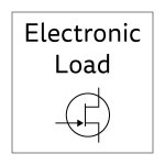
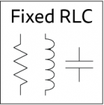
Fixed-load.png | The fixed load section allows PCBs with different R, RL and RC loads to be connected to investigate current and voltage characteristics. | Fixed-load.png | The fixed load section allows PCBs with different R, RL and RC loads to be connected to investigate current and voltage characteristics. | ||
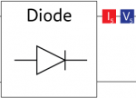
Battery-charger.png | This section provides a DC output from the board, measured by current and voltage sensors. A diode protects the board from the reverse flow of current. | Battery-charger.png | This section provides a DC output from the board, measured by current and voltage sensors. A diode protects the board from the reverse flow of current. | ||
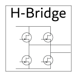
| − | + | H-bridge.png | The H-bridge circuit allows AC to be generated from the DC output of the solar panel or rectifier, modelling grid connection. | |
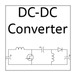
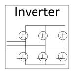
Inverter.png | A MOSFET based inverter topology is used on our PCB as a controlled three-phase rectifier, allowing the wind turbine output to be used with the DC-DC converter and MOSFET load. | Inverter.png | A MOSFET based inverter topology is used on our PCB as a controlled three-phase rectifier, allowing the wind turbine output to be used with the DC-DC converter and MOSFET load. | ||
| − | |||
|} | |} | ||
</gallery> | </gallery> | ||
| − | == | + | == Software Architecture Design== |
| − | === | + | |
| − | The | + | === Robot's Core Tasking Handling State Machine=== |
| − | + | ||
| − | + | <p>A state machine model has been developed for the robot as shown in the picture below. This model encapsulates all of the actions that the robot is required to do as per the competitions requirements. This model will be used to help implement the state machine design pattern in LabVIEW.</p> | |
| + | [[File:Statemachine.png | frame | center | x400px | State Machine Diagram ]] | ||
| + | [[File:Staterecord.PNG | frame | center | x300px | LabVIEW State Machine ]] | ||
| + | |||
| + | '''Path Finding Algorithms''' | ||
| + | |||
| + | The A* search algorithm is a widely used path-finding method which describes a process for plotting an efficiently traversable path between nodes. It is an example of the approximate cell decomposition strategy mentioned previously. Each node is a cell with a cost function for traversing it. The simplest case denotes 100 (the maximum value) for cells which cannot be traversed and 0 (the minimum) for cells which contain free space and the algorithm computes the lowest expected cost path for the robot. It is an extension of Dijkstra’s algorithm4 which has inspired a number of variants that include the D* lite algorithm | ||
| + | |||
| + | [[File:Codepathfind.PNG| 500px | ]] | ||
| + | |||
| + | |||
| + | === Vision System Design=== | ||
| + | |||
| + | '''Kinect Camera''' | ||
| + | |||
| + | Kinect Camera (or Kinect Sensor) is an integrated sensor array which is designed by Microsoft as an user interact gaming consoler. It contains of an infrared sensor and high resolution camera which is capable for the input device of the robot’s vision system. The reason for choosing the Kinect camera is because of its inexpensive, easy of deployment and versatile functions for different applications. A picture below showed the structure of the Xbox 360 Kinect Camera. | ||
| + | |||
| + | [[File:Kinect.png| 400px | ]] | ||
| + | |||
| + | '''Image Processing Path''' | ||
| + | |||
| + | A picture below shows the image processing method used by Kinect Camera: | ||
| + | |||
| + | [[File:Imageprocess.png| 500px | ]] | ||
| + | |||
| + | A: IMAQ ColourThreshhold, applies the threshold on three planes of an RGB or HSL image and place the result in an 8-bit image output as “Image”. | ||
| + | |||
| + | B: IMAQ Remove Particle, Eliminate or keeps the particles resistant to a certain number of 3 by 3 image. In another word, this function fill in the particles to make the targeting area consistent when it is showed on the 8bit image map. | ||
| + | |||
| + | C: IMAQ Centroid, compute the centre of the energy of the image or a portion of the image. | ||
| + | |||
| + | |||
| + | === Motor Control Program=== | ||
| − | + | '''Forward/Backward''' | |
| + | This Program has a case control mechanism which depends on the input Turning on off signal and the feed back signal from the comparison logic. | ||
| − | + | The reason for using this logic is because it would be easy to control the motor movement and set delay for motor to react. | |
| − | The | ||
| − | |||
| − | |||
| − | [[File: | + | [[File:ForwardVI.png| 600px | ]] |
| − | + | '''Rotate Left/Right''' | |
| − | |||
| − | |||
| − | = | + | Still using case control mechanism, however, there are two differet cases in this program. The first case in the middle is the different actions of turning left / right. First the VI would determine the input angle to see whether its >0, (Turn Left), <0,(Turn Rigt) or =0(End Loop). Then it would calculate the real distance for the input angle and compare with the actual distance from the encoder feedback. Last step is the second feedback case for controling the motor enable logic. Still there's an turning ON/OFF signal to stop the motor and exit the loop. |
| − | + | [[File:Coderotate.PNG| 600px | ]] | |
| − | |||
| − | [[File: | ||
== Future Work == | == Future Work == | ||
Latest revision as of 08:59, 5 June 2015
This project is focus on designing and building up an autonomous robot by utilizing the integrated microcontroller FPGA called MyRIO Device provided by National Instrument, which is based the requirements of 2014 National Instruments Autonomous Robotics Competition (NI ARC).
Contents
Project Overview
Project Aims
The aim of the project is to design and build an autonomous robot that would be able to satisfy the requirement in National Instruments Autonomous Robotics Competition 2014 (NI ARC). The key robotics area of this year's competition is path planning, obstacle avoidance and object handling. Our group isn’t took part in the competition due to the different timings of the honours project and competition. Nonetheless the rules and guidelines of the competition provide the specifications for the robot that the group will design and build. For the competition, teams must use the NI MyRIO device and the LabVIEW development environment to program the majority of the code for the robot.
Project Introduction
Each year, National Instruments (NI) sponsors a competition to showcase the robotics capabilities of students by building autonomous robots using one of their microcontroller and FPGA products. In 2014, the competition focuses on the agriculture setting where the robots will need to communicate with a device, collect seeds, navigate an obstacle course, and then deposit the collected seeds. The key robotics application focus areas for the 2014 competition are:
- Obstacle avoidance
- Object handling
- Navigation
This project investigates the use of the NI FPGA/LabVIEW platform for autonomous vehicles. The requirements of the competition will form the basis of the desired project outcome. The autonomous robot is mainly contains of three major parts for development: software algorithm and architecture design, vision system design, and hardware system design. The project would require basic electrical knowledge, mechanical knowledge and software programming to build the required robot. The rules and guidelines of the competition provide the competing teams and our honours group with the functional requirements of the robot. This information will therefore define the scope of the honours project. The rules for the time limits and points scoring scheme will be omitted as they do not affect the design of our robot. The competition objectives are:
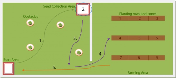
- The robot will begin from the Start Area and make its way to the Seed Collection Area. Bumping into any obstacle or wall during its way to the Seed Collection Area will result in a penalty.
- Once the robot has reached the Seed Collection Area, a team member (simulating a conveyor system) will load a number of seeds onto the robot to be transported to the Farming Area.
- The robot must make its way to the opening of the Farming Area. Again, bumping into any obstacle or wall will result in a penalty.
- Using the coordinates received prior to commencing the task, the robot must navigate to the best ploughed row and zone to plant the seeds. The robot continues planting at the next best zones until it has run out of seeds. The robot must drop the seeds within the specified area.
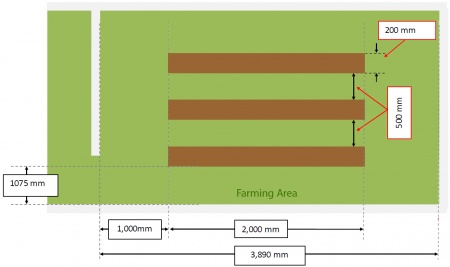
The graph below show the objectives with on the competition track as well as the dimensions of the track and the farming area. The planting rows and zones are not labelled on the physical track so the robot cannot use visual cues for where to plant the seeds. Each planting row and zone has equal size.
Previous Studies
Robotic as one of the most heated application in electrical and mechanical engineering, a lot of work and example were done by other people in the past decades. These robots would be having a wide range which including quad copters, kinetic robots, vehicle models, and industrial robot applications etc. For the student orientated autonomous robot the most common ones are known as the Arduino, NXT (Lego) robots, the National Instrument robot and other related microprocessor based robotics. However, the main difference of our project when compared with the others, is that we will be utilizing the NI MyRIO devices which is a recent product lunched by National Instrument, and we are the first batch of people who is focus on the development of autonomous robot based on the MyRIO device. So there might not be much information available in regards of the MyRIO robotics development. Yet the previous example robot and projects could be a good way to approach this project design, as the principle and consideration for building up a robot is similar in a scale. For the National Instrument robotics, the previous project and competition is mainly focus on the CompactRIO Device, which is quite similar to ours and could be a reference for developing our own robots.
Objectives of the project
The major goal of this project is to develop a completed autonomous robot which would be including different objectives for robot's software and hardware system
This will be including:
• Building a robot base to carry all the hardware components.
• Implementing the MyRIO device and all the required sensors to the robot
• Developing LabVIEW programs to control the robot and achieve the required function
Hardware Component and Detail Design
MyRIO Device Introduction
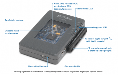
The NI myRIO device is a highly integrated FPGA microcontroller device which has been designed for students to learn about robotics and mechatronic systems. It supports the LabVIEW reconfgurable I/O (RIO) architecture and can be programmed using the LabVIEW programming language and development environment.
The myRIO device will act as the processing unit for the robot which needs to handle the majority of processing on the robot as required by the competition rules. Its interfaces include two sets of Expansion Ports (MXP) and a Mini System Port (MSP) which contain an analog input channels, six analog output channels and forty digital I/O channels as well as audio and power output. It can connect to a host computer via USB or wireless 802.11bgn which is very convenient as it can be programmed and controlled wirelessly. It also contains a programmable button and LEDs which can be used to demonstrate simple programs. The device contains a dual-core ARM processor which combines the software programmability of a processor with the hardware programmability of an FPGA. Its processing power is more than adequate to handle the computations that will be required by the autonomous robot. A picture below shows the layout of the National Instrument MyRIO device.
Power System Architecture
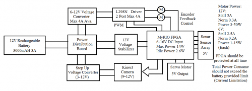
As an essential requirement of electronic device, power must be provided in order to support all the internal components function well. Without power all the electronics would not be able to run, hence power is indispensible and the fundamental attributes of all the robots. For this specific autonomous robot system, power source should be portable and powerful enough to supply the main energy consumption from robot’s motion system, as well as supporting all the other components in various situations. When considered about power system design, it could generally be developed into three sessions: overall power system design, selection of power source and detail design of the power circuits.
The diagram above illustrates the architecture of our robot power system. In order to satisfy the mobile and portable requirements of the autonomous robot, we would be using DC battery as the main power source. The battery output connects into a power distribution board, which then separates into multiple channels, for our distribution board we have implemented 5 different channels for future applications.there are only three main channels presented in the diagram.
One channel is designed for the locomotion system only as it's the largest power consumption system of our robot.The gear motor would have the potentials of drawing very high current at stall situations, so we consider the worst condition that if both of the motor is stalling at maximum speed operations, which would draw up to 5Amps current and the distribution board should be able to sustain without causing any damages or instabilities.
The second channel is dedicated for the MyRIO device only, as it's the most important yet vulnerable components of the entire robot system, so we designed it to be isolated from the other channels which would be able to minimize the interferences from other channels, as well as protecting from instantaneous surge current causing by the motors and other components.
The third channel is allocated to the Kinect camera (sensor), since its small voltage range support we have discussed before, even though it's a well integrated module and robust for power variation, it still needs stable power condition to operate properly.
Battery
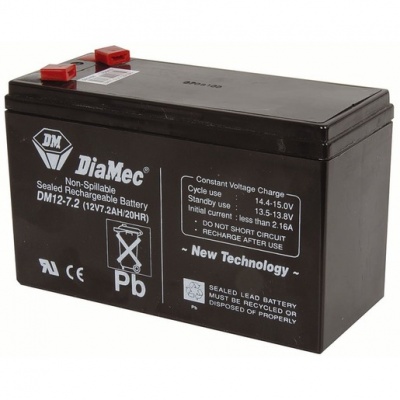
This is the battery that we’ve installed on our final robot, it’s a 12V 2200mAh battery which has a rated continuous discharge current of 7.2AH, and could be able to support up to 40A surge current for a short period of time (5 sec), according to its specifications. It comes with a size of 150 (L) x 65 (D) x 93 (H) mm with approximate weight of around 1 kilogram.
Distribution Board
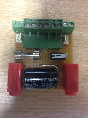
The design of our power distribution is presented as follow:It’s a simple power distribution method by separating different channel using terminal blocks and multiple copper lines at the back, which would be easily modified and disassembled for future developments. The concept of this design is to make everything removable and portable so the user would be very convenient to modify the circuit and disconnect the unwanted components.
As the robot’s power source is determined as a DC battery, which would only provide a single voltage level and would be continuous dropping as the operation time moves on. However, for our robot subsystems to function correctly and maintain stable under different situations, we need to implement DC converters to transform the battery voltage into different levels, in order to support different components deployment. And we also need voltage regulator to stabilize the input voltage of the power sensitive devices, so that the robot could be able to operate properly in different battery conditions, as well as preventing potential damage from overvoltage or undervoltage of the battery output. On another aspect, the implementation of DC converter and voltage regulator would extend the robot’s ability of voltage dependency that even with different set of battery, as long as it provides enough current draw to the system, it could be able to support the robot power system in normal operations.
Flyback Converter for MyRIO Device
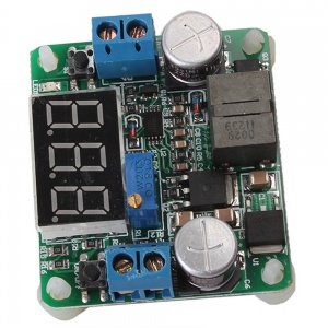
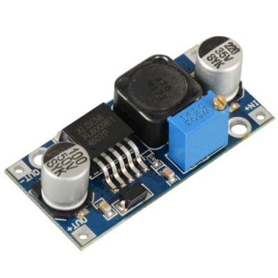
The flyback converter we have chosen is a 5-25V Buck Boost DC Converter with a LED display that could be able to show the voltage level of both input and output terminals. The diagram of this converter is illustrated as below:
Inverting Converter for Motion System
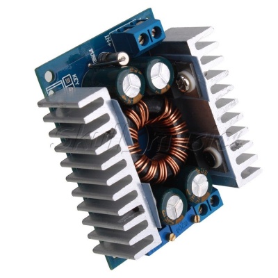
The main reason for installing this module is to control to motor’s speed by adjusting the output voltage sent to the motor driver board.
Inverting Converter for Kinect Sensor
The chip integrated converters are inexpensive, small in size, and usually possess compatible specifications. Because Kinect Sensor is not high power consumed, resistant to interferes, and robust in different conditions, so we picked a XL6009 Buck Boost Converter which would be able to support up to 4A
Final Robot Construction
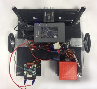
The final robot platform is presented as follow, we have integrated the motoion system, power system as well as different sensors together and mounted on a two layer acrylic base, which would be able to moving around and scan the environment to plan its path to destination and to avoid obstacles.
Locomotion System Design
Locomotion system is an important and indispensable part for an autonomous vehicle robot, as it provides the basic function for robot to move from place to place. Referred to the National Instrument competition task, the designed robot should be able to achieve navigation and obstacle avoidance, thus a good locomotion system will carry the robot through challenging environment condition and enhance the robot performance of dealing with multiple task requirements. The locomotion system design mainly contains of five sections: Mechanism Structure Design, Motor Selection, Motor Driver Selection and Motor Control System. These five sections, together with the MyRIO device and power source, formed up the entire locomotion system of the autonomous robot.
DC Motor
After detail research of the available selections from internet and local market, we have selected a 12V Gear DC Motor with a ratio of 43.7:1 and 250RPM to be the main driver motor, with an encoder feedback installed on the motor shaft. During the testing we’ve found out it’s a good selection for the locomotion system design, as it could provided enough power and speed to drive our robot. The motor specification is presented as follow:
Motor Driver
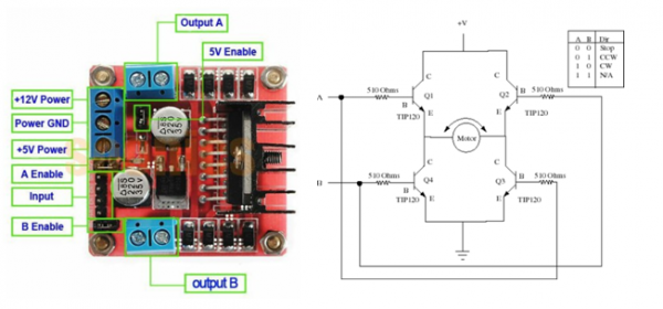
Since the MyRIO device could not provided enough power to the motors mainly due to current limit of the output supply, a motor driver is required to supply large power consumption from DC motors. The power source of motors should be the battery itself, and the driver should be able to provide the required power output as well as compatible to interface with the MyRIO device.A suitable motor driver board for the has been determined, which is the L298N Dual H Bridge Motor Driver IC. This board would support 2 motor at 12V with a maximum current of 2A.The L298N motor driver board details is presented as follow:
Motor Control System
A picture below shows the general motor control system design of the robot:
Where the motion controller is represented as the MyRIO device, it controls the entire locomotion system and process the position command to send the signal to the amplifier. The amplifier is referred to motor driver board, which provides the power to the motor and transfer the control signal to drive the motor. There are also feedback signals from motors to reflect the velocity and position of the moving robot. The encoder feedback is basically consisted of two Hall Effect sensors, which are magnetic to detect the magnetic field change by motor spinning, based on the frequency and direction of the pulse signal from two different sensors, the MyRIO device would be able to calculate the velocity and traveled distance of each motor.
Design Circuits Illustration
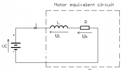
| DC Motor Equivalent Circuit |
| Flyback Converter |
- Circuits
Software Architecture Design
Robot's Core Tasking Handling State Machine
A state machine model has been developed for the robot as shown in the picture below. This model encapsulates all of the actions that the robot is required to do as per the competitions requirements. This model will be used to help implement the state machine design pattern in LabVIEW.
Path Finding Algorithms
The A* search algorithm is a widely used path-finding method which describes a process for plotting an efficiently traversable path between nodes. It is an example of the approximate cell decomposition strategy mentioned previously. Each node is a cell with a cost function for traversing it. The simplest case denotes 100 (the maximum value) for cells which cannot be traversed and 0 (the minimum) for cells which contain free space and the algorithm computes the lowest expected cost path for the robot. It is an extension of Dijkstra’s algorithm4 which has inspired a number of variants that include the D* lite algorithm
Vision System Design
Kinect Camera
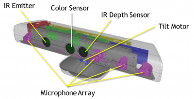
Kinect Camera (or Kinect Sensor) is an integrated sensor array which is designed by Microsoft as an user interact gaming consoler. It contains of an infrared sensor and high resolution camera which is capable for the input device of the robot’s vision system. The reason for choosing the Kinect camera is because of its inexpensive, easy of deployment and versatile functions for different applications. A picture below showed the structure of the Xbox 360 Kinect Camera.
Image Processing Path
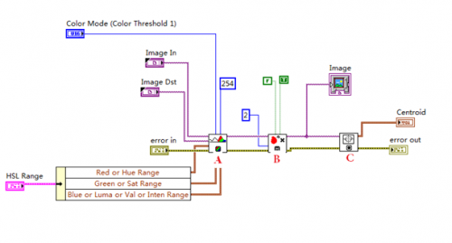
A picture below shows the image processing method used by Kinect Camera:
A: IMAQ ColourThreshhold, applies the threshold on three planes of an RGB or HSL image and place the result in an 8-bit image output as “Image”.
B: IMAQ Remove Particle, Eliminate or keeps the particles resistant to a certain number of 3 by 3 image. In another word, this function fill in the particles to make the targeting area consistent when it is showed on the 8bit image map.
C: IMAQ Centroid, compute the centre of the energy of the image or a portion of the image.
Motor Control Program
Forward/Backward
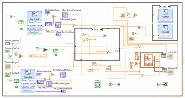
This Program has a case control mechanism which depends on the input Turning on off signal and the feed back signal from the comparison logic.
The reason for using this logic is because it would be easy to control the motor movement and set delay for motor to react.
Rotate Left/Right
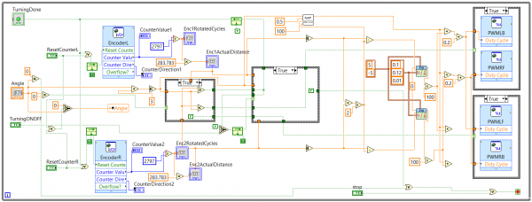
Still using case control mechanism, however, there are two differet cases in this program. The first case in the middle is the different actions of turning left / right. First the VI would determine the input angle to see whether its >0, (Turn Left), <0,(Turn Rigt) or =0(End Loop). Then it would calculate the real distance for the input angle and compare with the actual distance from the encoder feedback. Last step is the second feedback case for controling the motor enable logic. Still there's an turning ON/OFF signal to stop the motor and exit the loop.
Future Work
As our project timeline is close to the end, hence we might not be able develop the new functions and tested out in the field. However, as a pioneer of the MyRIO robotics development, our work would be of great benefit to those people who will be continuing for our project. For the object handling design, we haven’t implement a comprehensive mechanism which could be further developed as a robot arm or spinning wheels that could handle multiple seed collection. For the locomotion system, we’ve been only using a two wheel control system which is difficult to achieve turning movement, for future development it could be upgraded to a four wheel drive system or design a powerful control program which would be able to turn during forward or backward movement.
Team Management
Team Members
- Mr Jiannan Li
- Mr Martin Nobis
- Mr Zhanxiang Gong
Supervisors
- Prof Cheng Chew Lim
- Dr Hong Gunn Chew
Team Member Responsibilities
Group 74 has three members and the responsibilities have been allocated as follows:
- Zhanxiang is responsible for all the robot hardware design, testing and installation, which includes the power system ,motion system and the chassis / layout of the robot
- Martin is responsible for the robot software architecture design, which mainly includes the LabVIEW program development for the robot's internal system
- Jiannan is responsible for the robot's sensor deployment, which mainly about developing the vision system using Xbox Kinect Sensor and delopying the sonar sensor for the robot
Project Timeline
Starting at the beginning of August 2014,The final year project lasts for one academic year which contains of 24 working weeks in total. However, the actual working schedule might not be 24 weeks since we only have 10 weeks in semester 2 to finish all the required parts before the final demonstration. And we could also utilize the holiday period to perform our works although it is not recommended. There are three main milestones throughout the whole project, which are: Milestone 1 MyRIO basic I/O Interfacing Milestone 2 Prototype Robot Development Milestone 3 Final Robot Construction
Resources
- Computer
- DC Power Supply
- Laboratory Benches
- Oscilloscope
- Signal Generator
- LabVIEW 2014 Software
- NI MyRIO Device
- Soldering Stations
