Difference between revisions of "Projects:2015s1-21 Inexpensive Portable Radar System"
(→Project High Level Design) |
(→Student Members) |
||
| (31 intermediate revisions by 3 users not shown) | |||
| Line 2: | Line 2: | ||
Radars operate on the principle of echolocation; they transmit an electromagnetic radio wave and analyse any reflected wave (or echo) to gather information regarding potential targets. These targets can include cars, planes, and clouds. This project involves improving an existing radar system which is based on the MIT Coffee Can Radar. The project has combined the hardware and software elements of RF engineering to produce a completely portable system which operates on the 2.4 GHz Wi-Fi band and is capable of two different modes. These modes are the Doppler mode which calculates a targets speed, and the Range mode which calculates its distance. The primary aims of this year’s project was to improve the radars portability, decrease its cost, and increase its functionality. | Radars operate on the principle of echolocation; they transmit an electromagnetic radio wave and analyse any reflected wave (or echo) to gather information regarding potential targets. These targets can include cars, planes, and clouds. This project involves improving an existing radar system which is based on the MIT Coffee Can Radar. The project has combined the hardware and software elements of RF engineering to produce a completely portable system which operates on the 2.4 GHz Wi-Fi band and is capable of two different modes. These modes are the Doppler mode which calculates a targets speed, and the Range mode which calculates its distance. The primary aims of this year’s project was to improve the radars portability, decrease its cost, and increase its functionality. | ||
| − | |||
| − | |||
==Background== | ==Background== | ||
| Line 36: | Line 34: | ||
This project is primarily being undertaken to expand on team members knowledge on radar and related areas, which have previously been unexplored. Such areas include programming, RF design, and power supply. The final product shall be used by the continuing honours team next year and eventually as a classroom demonstration tool. With the potential of becoming a teaching instrument, many future students may benefit from the successful completion of this project. | This project is primarily being undertaken to expand on team members knowledge on radar and related areas, which have previously been unexplored. Such areas include programming, RF design, and power supply. The final product shall be used by the continuing honours team next year and eventually as a classroom demonstration tool. With the potential of becoming a teaching instrument, many future students may benefit from the successful completion of this project. | ||
| − | |||
| − | |||
| − | |||
| − | |||
| − | |||
| − | |||
| − | |||
| − | |||
| − | |||
| − | |||
| − | |||
| − | |||
| − | |||
| − | |||
| − | |||
| − | |||
| − | |||
| − | |||
| − | |||
| − | |||
| − | |||
| − | |||
| − | |||
| − | |||
| − | |||
| − | |||
| − | |||
| − | |||
| − | |||
| − | |||
| − | |||
| − | |||
| − | |||
| − | |||
| − | |||
| − | |||
| − | |||
| − | |||
| − | |||
| − | |||
| − | |||
| − | |||
| − | |||
| − | |||
| − | |||
| − | |||
| − | |||
| − | |||
| − | |||
| − | |||
| − | |||
| − | |||
| − | |||
| − | |||
| − | |||
| − | |||
| − | |||
| − | |||
| − | |||
| − | |||
| − | |||
| − | |||
| − | |||
| − | |||
| − | |||
| − | |||
| − | |||
| − | |||
| − | |||
| − | |||
| − | |||
| − | |||
| − | |||
| − | |||
| − | |||
| − | |||
==Project Aims and Objectives== | ==Project Aims and Objectives== | ||
| Line 146: | Line 68: | ||
If these proposed objectives are implemented, the finished product will move closer to its desired final state of being a truly inexpensive, portable radar. Such a radar has the capability of being continued on as a Honours Project with a different focus or becoming a classroom teaching tool for the university. | If these proposed objectives are implemented, the finished product will move closer to its desired final state of being a truly inexpensive, portable radar. Such a radar has the capability of being continued on as a Honours Project with a different focus or becoming a classroom teaching tool for the university. | ||
| + | |||
| + | ==Project High Level Design== | ||
| + | |||
| + | The following steps outline how the systems individual components interact together to produce a working radar. | ||
| + | :'''Step 1:''' Voltage Output- The On-Board Processor, a Raspberry Pi, outputs a voltage through its audio jack and into the RF System. | ||
| + | :'''Step 2:''' Wave Generation and Transmission- The RF System generates a wave to be transmitted. The frequency of this wave is determined by the voltage input into the system. The wave is then transmitted through the Tx Antenna. | ||
| + | :'''Step 3:''' Receive Wave and Mixing- If a target is present, the transmitted wave will reflect off of the target and echo back towards the radars Rx Antenna. This received wave is then mixed with the transmitted wave in the RF system to produce a wave at their frequency difference, the IF wave. | ||
| + | :'''Step 4:''' Signal Filtering and Amplification- The IF wave is output from the RF system and into the Video Amplifier. The video amplifier filters out all frequencies above 15kHz and amplifies the signal. | ||
| + | :'''Step 5:''' Signal Processing and Display- The video amplifier passes the signal back to the On-Board Processor. The processor takes the FFT of the signal and displays the appropriate results on the On-Board Display. | ||
| + | |||
| + | [[File:2015Radar.png|750px]] | ||
==2015 Honours Radar== | ==2015 Honours Radar== | ||
| + | |||
The 2015 Honours radar has the following characteristics; | The 2015 Honours radar has the following characteristics; | ||
*FMCW Waveform | *FMCW Waveform | ||
| Line 155: | Line 89: | ||
*1.79m range resolution | *1.79m range resolution | ||
| + | ===Objective 1; Reimplementing Processing Procedure=== | ||
| + | ====Software Design==== | ||
| + | The software design for this project was based on the 2014 Honour’s groups Matlab code, adapting it to C++ and looping the main function to create continual data output. The design was developed in 5 steps: Breaking down the existing code, reorganizing the components into a loop, exploring different C++ libraries to achieve the required functions and interfacing with hardware. | ||
| + | |||
| + | The resulting design is shown in the flowchart below. | ||
| + | |||
| + | [[File:2015design.png]] | ||
| − | === | + | ====Testing==== |
| + | Each major section of the software was tested with generated inputs from Matlab, with the results verified in Matlab. It was found that the use of audio as an output method was not suitable and so a hardware generated signal had to be implemented for input to the VCO. All other sections of the code worked as planned. | ||
| + | The resulting software design was able to produce a plot which represents the frequencies with the greatest amplitude in the received signal. The image below shows the graphical output for a 440Hz sine wave input. | ||
| + | |||
| + | [[File:440HzSinewave.png]] | ||
===Objective 2; Implementing an Interface=== | ===Objective 2; Implementing an Interface=== | ||
| + | For the implementation of the interface, the Sainsmart 7" TFT touch screen display was used. This screen uses a driver board that is able to accept HDMI, VGA and AV inputs. The Raspberry Pi 2 has a built in HDMI, so this was used as the video output. | ||
| + | |||
| + | [[File:displaysteup.jpg]] | ||
===Objective 3; Reimplementing RF System=== | ===Objective 3; Reimplementing RF System=== | ||
| − | + | ====RF Design==== | |
The MIT RF system consists of SMA connected components in a simple | The MIT RF system consists of SMA connected components in a simple | ||
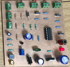
design which is easy to manufacture, has few areas of additional interference or noise, and can individually test each component. However, this system is large and costly. To achieve this objective it was decided to implement the RF system onto a PCB. The miniaturization of the RF system from these SMA connected components onto a PCB would reduce the size and cost of this system. The two designs can be seen in Figure 9. The PCB design does introduce many additional factors which can effect the performance of the system. The PCB architecture is based on that of the MIT design with appropriate SMD's replacing their counterpart SMA components. | design which is easy to manufacture, has few areas of additional interference or noise, and can individually test each component. However, this system is large and costly. To achieve this objective it was decided to implement the RF system onto a PCB. The miniaturization of the RF system from these SMA connected components onto a PCB would reduce the size and cost of this system. The two designs can be seen in Figure 9. The PCB design does introduce many additional factors which can effect the performance of the system. The PCB architecture is based on that of the MIT design with appropriate SMD's replacing their counterpart SMA components. | ||
| Line 167: | Line 115: | ||
The design of an analog PCB is critical as there are many factors that can effect the signal in the circuits transmission line. Generally, the circuit will be attempting to amplify and use one particular signal while rejecting all others including any noise present. This section will discuss the design rules, guidelines and optimization techniques used to design and implement a successful PCB circuit. It defines key characteristics and is then broken down into key areas and the design considerations that apply to them. | The design of an analog PCB is critical as there are many factors that can effect the signal in the circuits transmission line. Generally, the circuit will be attempting to amplify and use one particular signal while rejecting all others including any noise present. This section will discuss the design rules, guidelines and optimization techniques used to design and implement a successful PCB circuit. It defines key characteristics and is then broken down into key areas and the design considerations that apply to them. | ||
| − | + | [[File:NewRF_OldRF.png|540px]] | |
| + | |||
| + | ====RF Testing==== | ||
The RF system produced accurate results when tested with a cable, thus it was integrated with last years Honours system for full system testing. This included using the antennas. The power was supplied by a bench top power supply thus the testing had to be performed in the Honours labs. | The RF system produced accurate results when tested with a cable, thus it was integrated with last years Honours system for full system testing. This included using the antennas. The power was supplied by a bench top power supply thus the testing had to be performed in the Honours labs. | ||
| − | :''Range Mode Testing'' | + | :'''Range Mode Testing''' |
The Range mode results are shown below. The green line in these graphs indicates the distance the target is from the radar. | The Range mode results are shown below. The green line in these graphs indicates the distance the target is from the radar. | ||
| − | + | [[File:Range_NewRF_NewVAMP.png|200px]] | |
| − | :''Doppler Mode Testing'' | + | :'''Doppler Mode Testing''' |
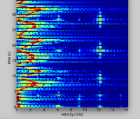
The Doppler mode results are shown below. The red in the graph indicates the speed of the target. | The Doppler mode results are shown below. The red in the graph indicates the speed of the target. | ||
| − | + | [[File:Doppler_NewRF_NewVAMP.png|200px]] | |
| − | |||
| − | |||
| + | ====RF Redesign==== | ||
| + | As the key challenges posed to us throughout the project were due to our lack of knowl- edge and experience. when the project went on, our skills improved and the challenges became less of an issue. This allowed us to continuously improve the RF system through the design stage, and achieve more accurate and relevant results in testing. | ||
| + | Upon evaluating our designs towards the end of the project, we were able to identify several key areas which could easily be improved. Such areas include adding bandpass filters into the system to reduce the interference of sidebands and noise as some of these sidebands harmonics and noise are not in range of Wi-Fi band. Also switching a few components for better models to improve important characteristics such as VSWR and IOP3. | ||
| − | + | ====Conclusion==== | |
The tests undertaken on the RF system alone did not provide conclusive data to indicate that the system worked as expected. This may be due to the fact that tests using the signal generator were inconsistent due to the fluctuating VCO frequency, and the tests including the cable were compared against approximate values. When the video amplifier and antennas were incorporated into the testing, the video amplifier initially worked as expected however the antennas introduced a large amount of noise (likely due to the crowded lab environment). When the RF system was integrated with the old video amplifier and the signal was processed and displayed, clear and accurate results were produced. In comparison to the the 2014 Honours radar the results produced were either the same or better. | The tests undertaken on the RF system alone did not provide conclusive data to indicate that the system worked as expected. This may be due to the fact that tests using the signal generator were inconsistent due to the fluctuating VCO frequency, and the tests including the cable were compared against approximate values. When the video amplifier and antennas were incorporated into the testing, the video amplifier initially worked as expected however the antennas introduced a large amount of noise (likely due to the crowded lab environment). When the RF system was integrated with the old video amplifier and the signal was processed and displayed, clear and accurate results were produced. In comparison to the the 2014 Honours radar the results produced were either the same or better. | ||
===Objective 4; Reimplementing Power Source=== | ===Objective 4; Reimplementing Power Source=== | ||
| + | DC to DC converter is very important in portable electronic device. Switched DC to DC converters can get the required voltage and it could save space instead of using more batteries. There are two main types of converters: such as step-down, step-up. Step down like buck converter, when the input voltage is higher than the output voltage. Step up like boost converter, when the input voltage is lower than the output voltage. The switch mode converter increases the running time of the battery operated the devices, and also reduces the size of the heatsink. The heat sink is not necessary in some cases. The linear regulator can provide a low noise output voltage which is very good for radio frequency circuit. | ||
| + | |||
| + | The input voltage is two 6 volts battery. To convert 12 V to 5V, the three terminal linear regulators are very popular which the 2014'd final year project group used in their design. LM2576 series simple switcher step-down voltage regulator has been used in this year’s design, because 3 terminal need larger heat sink and LM2576 didn't require any heat sink in some cases. The benefit of the LM2576 is requiring a min number of components and these regulators are simple to use. | ||
| + | |||
| + | [[File:outputvoltage1.png]] | ||
| + | |||
| + | ==== Implement All in One PCB ==== | ||
| + | All in one PCB could make the radar system smaller. "Power source, Video Amplifier" | ||
| + | |||
| + | [[File:All in one.png]] | ||
| + | |||
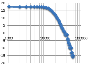
| + | video Amplifer testing: Gain(dB) VS frequency(Hz) | ||
| + | |||
| + | [[File:vedio.png]] | ||
===Objective 5; Implementing Radar Scanning=== | ===Objective 5; Implementing Radar Scanning=== | ||
| + | This is a new function for this project. The 28BYJ-48 with ULN2003 driver has been selected because it is the cheapest. Then install the Wringpi file for the GPIO, because the stepper motor is controlled by raspberry pi and connect to GPIO. The most important part is programming. | ||
| + | |||
| + | [[File:step.png]] | ||
| + | |||
| + | [[File:Wringpi.png]] | ||
| + | |||
| + | [[File:clock.png]] | ||
===Project Outcomes=== | ===Project Outcomes=== | ||
Even though this project faced many challenges and set backs, overall it has accomplished the aims which were set out, exceeding these in some areas by introducing the theory required to improve the radars characteristics. This project has also accomplished in greatly improving the depth of RF engineering knowledge, PCB design and testing, and general project management of team members. If this project is continued next year there are many areas which can be improved upon, however this years project team has definitely moved the project forward towards the future goal of this radar being used as a teaching tool. | Even though this project faced many challenges and set backs, overall it has accomplished the aims which were set out, exceeding these in some areas by introducing the theory required to improve the radars characteristics. This project has also accomplished in greatly improving the depth of RF engineering knowledge, PCB design and testing, and general project management of team members. If this project is continued next year there are many areas which can be improved upon, however this years project team has definitely moved the project forward towards the future goal of this radar being used as a teaching tool. | ||
| + | |||
| + | ==Results== | ||
| + | |||
| + | ===Doppler Mode=== | ||
| + | |||
| + | The Doppler mode is used to determine the velocity of a target in relation to the radar. To achieve this the Doppler Effect is used. The Doppler Effect is the change of the transmitted waves frequency due to a moving target. The output of the Doppler mode is shown in Figure 3. This figure represents a target increasing its speed to 3m/s, slowing to a stop and then repeating this process. | ||
| + | |||
| + | [[File:Doppler_NewRF_NewVAMP.png|540px]] | ||
| + | |||
| + | ===Range Mode=== | ||
| + | |||
| + | The Range mode is used to determine the distance a target is from the radar. To accomplish this a linear FM chirp needs to be transmitted. The reflected wave is received a short time after transmission, and as the transmitted wave is a chirp the received wave will be at a slightly different frequency. This frequency difference is used to calculate the targets range. The output of the Range mode is shown in Figure 4. This figure represents a target moving from in front of the radar to a range of 10m away and back. | ||
| + | |||
| + | [[File:Range_NewRF_NewVAMP.png|540px]] | ||
| + | |||
| + | ==Conclusion== | ||
| + | |||
| + | This project faced many challenges and set backs, overall it has accomplished the aims which were set out, exceeding these in some areas by introducing the theory required to improve the radars characteristics. This project has also accomplished in greatly improving the depth of RF engineering knowledge, PCB design and testing, and general project management of team members. If this project is continued next year there are many areas which can be improved upon, however this years project team has definitely moved the project forward towards the future goal of this radar being used as a teaching tool. | ||
| + | |||
| + | ==Future Work== | ||
| + | |||
| + | :* Integrating all modules into one PCB | ||
| + | :* Using different band e.g. 5GHz | ||
| + | :* Improve output Graphs | ||
| + | |||
| + | ==Project Team== | ||
| + | |||
| + | ===Student Members=== | ||
| + | |||
| + | *'''Mohammad Hasan:''' | ||
| + | Bachelor of Engineering (Honours)(Telecommunications) | ||
| + | |||
| + | *'''Kieren Nelson:''' | ||
| + | Bachelor of Engineering (Honours)(Electrical and Electronic) | ||
| + | |||
| + | *'''Angus Reid:''' | ||
| + | Bachelor of Engineering (Honours)(Electrical and Electronic) | ||
| + | with Bachelor of Mathematical and Computer Science | ||
| + | |||
| + | *'''Wenkai (Kelvin) Zhu:''' | ||
| + | Bachelor of Engineering (Honours)(Electrical and Electronic) | ||
| + | |||
| + | ===Academic Supervisors=== | ||
| + | |||
| + | *'''Dr Brian Ng''' | ||
| + | : | ||
| + | |||
| + | *'''Dr Hong Gunn Chew''' | ||
| + | : | ||
| + | |||
| + | ==References== | ||
| + | |||
| + | [1] G. Charvat, J. Williams, A. Fenn, S. Kogon, and J. Herd, ”Build a Small Radar System Capable of Sensing Range, Doppler, and SyntheGc Aperture Radar Imaging,” Open Course Ware, Apr. 2011. [Online]. Available: hNp://ocw.mit.edu/ resources/. [Ac- cessed: Apr. 15, 2015]. | ||
Latest revision as of 14:23, 23 October 2015
Contents
- 1 Introduction
- 2 Background
- 3 Motivation
- 4 Project Aims and Objectives
- 5 Project High Level Design
- 6 2015 Honours Radar
- 7 Results
- 8 Conclusion
- 9 Future Work
- 10 Project Team
- 11 References
Introduction
Radars operate on the principle of echolocation; they transmit an electromagnetic radio wave and analyse any reflected wave (or echo) to gather information regarding potential targets. These targets can include cars, planes, and clouds. This project involves improving an existing radar system which is based on the MIT Coffee Can Radar. The project has combined the hardware and software elements of RF engineering to produce a completely portable system which operates on the 2.4 GHz Wi-Fi band and is capable of two different modes. These modes are the Doppler mode which calculates a targets speed, and the Range mode which calculates its distance. The primary aims of this year’s project was to improve the radars portability, decrease its cost, and increase its functionality.
Background
History
Radar is an acronym for RAdio Detection And Ranging. As its name implies, a radar system uses radio waves to detect and capture information regarding distant targets. This information can include the targets range, velocity, or shape. Radar first became industrialised in WWII, however its development began well before then. The first operating radar was built in 1904 by the German Christian Hulsmeyer. This device was a CW radar operating at 650MHz and was capable of detecting ships at sea within 3.2km, however it was unable to determine their distance or movement. The radar was developed concurrently by multiple nations, one of which was the United States. For the US, true progress began in 1934 when Robert M. Page was able to track a plane 1.6km away using a 60MHz pulse radar. With the evolution of the electronics industry, in particular digital to analog converters, the radar has continued to develop to this day. Modern radars are capable of a large number of functions including search, surveillance, target tracking, fire control, and weather monitoring. The use of digital systems has allowed modern radars to increase their sensitivity and overcome performance restrictions from problems such as clutter.
Radar Principle
The basic principle of how a radar works is stated below.
- A RF signal is transmitted towards a target.
- If the signal hits the target, it will be reflected or scattered off of it. Some of this reflected signal, or echo, will be directed back towards the radar system.
- The echo is picked up by the receive antenna of the radar system and is processed for the desired information.
The following radar equation shows how specific radar characteristics relate to one another. Pr = (Pt)G^2*sigma(lambda)^2/((4pi)^3(R)^4)
It can be seen that as the distance of the target R increases the received power, Pr, decreases at a rate of R^4. This indicates that the range of the target plays a crucial role in the radars performance.
Radar Types
The functionality and application of a particular radar depends on several factors including which frequency it operates at, what type of waveform is transmitted, antenna style and placement, and scan strategies. Several radar variations are described below.
- Bistatic and Monostatic Radar; A bistatic radar is one where the transmit and receive antenna are seperated by a significant distance (comparable to the target distance). A monostatic radar is one where the transmit and receive antenna are at the same location.
- Passive Radar; A passive radar is one which is able to detect a target by processing reflections from non-cooperative sources such as communication or broadcast towers.
- Planar Array Radar; This type of radar uses a high-gain planar array antenna. All of the elements in the antenna array are in the same plane, and are capable of directing the transmit signal by varying the relative phase of each element.
- Pulse-Doppler Radar; This radar system determines the range of a target using a pulse wave, and uses the Doppler effect of the received signal to determine the object speed. This method combines the features of the pulse and continue wave radars.
- Monopulse Radar; A monopulse radar splits the transmit beam into two beams, resulting in two signals being transmitted from the radar in slightly different directions. The received signals are amplified separately and then compared. The stronger of the receive signals indicates the general direction of the target. This method is capable to be used to track a target and is used by most modern radars.
- Over the Horizon (OTH); OTH radars are systems capable of detecting targets which are beyond an ordinary radars horizon. Two common methods that can be used to achieve this are to reflect the signal off of the atmosphere, or to use low-frequency radio waves that
follow the curvature of the earth due to refraction.
Motivation
This project is primarily being undertaken to expand on team members knowledge on radar and related areas, which have previously been unexplored. Such areas include programming, RF design, and power supply. The final product shall be used by the continuing honours team next year and eventually as a classroom demonstration tool. With the potential of becoming a teaching instrument, many future students may benefit from the successful completion of this project.
Project Aims and Objectives
This years Inexpensive, Portable Radar Project team shall focus on three distinct project aims;
- 1. Reduce Cost- Produce a final product that is cheaper than last years product of $700.
- 2. Improve Portability- Reduce the overall size of the project (~500x200x200mm) by 30%.
- 3. Add new functionality- Implement at least one new function to the system.
It was decided to accomplish these aim by undertaking the following objectives:
1. Reimplementing Processing Procedure:
- An onboard processor shall process all data, removing the need of a laptop and MATLAB licence. The processor will be required to process the radar data and produce images for both the Range and Doppler mode.
2. Implementing an Interface:
- A small, portable screen shall be used as the output of the system to display data processed by the Raspberry Pi via a customised GUI. A 7inch touch screen is available from last years project.
3. Reimplementing RF System:
- A new PCB RF system shall replace the current, bulky system as PCB RF components are significantly smaller and cheaper.
4. Reimplementing Power Source:
- With new system components, it has been found that a new range of voltages may be required for the system. This requires a new power distribution method which is capable of outputting powers of 6 and 12W (potential to change as system design finalised) and is sufficiently powerful enough to run all components.
5. Implement Radar Scanning:
- A rotation system shall be added onto the radar allowing it to calculate the distance of multiple objects in different directions from a single location.
If these proposed objectives are implemented, the finished product will move closer to its desired final state of being a truly inexpensive, portable radar. Such a radar has the capability of being continued on as a Honours Project with a different focus or becoming a classroom teaching tool for the university.
Project High Level Design
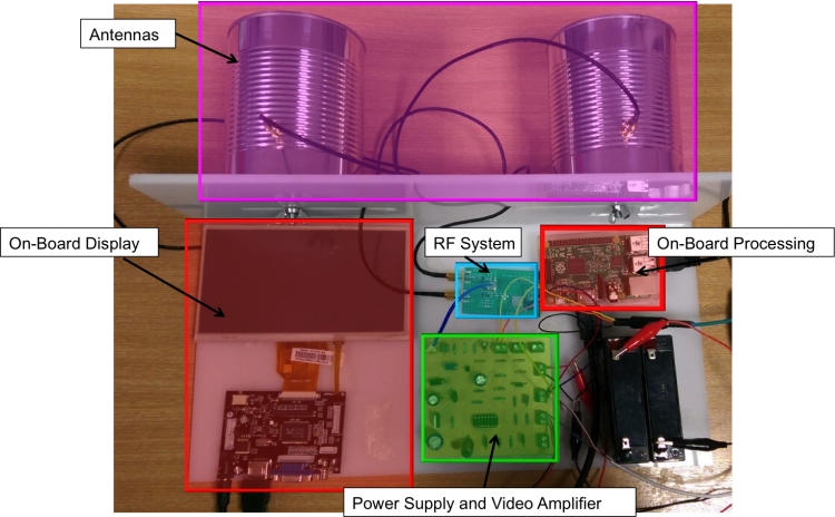
The following steps outline how the systems individual components interact together to produce a working radar.
- Step 1: Voltage Output- The On-Board Processor, a Raspberry Pi, outputs a voltage through its audio jack and into the RF System.
- Step 2: Wave Generation and Transmission- The RF System generates a wave to be transmitted. The frequency of this wave is determined by the voltage input into the system. The wave is then transmitted through the Tx Antenna.
- Step 3: Receive Wave and Mixing- If a target is present, the transmitted wave will reflect off of the target and echo back towards the radars Rx Antenna. This received wave is then mixed with the transmitted wave in the RF system to produce a wave at their frequency difference, the IF wave.
- Step 4: Signal Filtering and Amplification- The IF wave is output from the RF system and into the Video Amplifier. The video amplifier filters out all frequencies above 15kHz and amplifies the signal.
- Step 5: Signal Processing and Display- The video amplifier passes the signal back to the On-Board Processor. The processor takes the FFT of the signal and displays the appropriate results on the On-Board Display.
2015 Honours Radar
The 2015 Honours radar has the following characteristics;
- FMCW Waveform
- 2.4 to 2.5GHz operating frequency
- 12 to 12.5cm wavelength
- Monostatic antenna positioning
- 1.79m range resolution
Objective 1; Reimplementing Processing Procedure
Software Design
The software design for this project was based on the 2014 Honour’s groups Matlab code, adapting it to C++ and looping the main function to create continual data output. The design was developed in 5 steps: Breaking down the existing code, reorganizing the components into a loop, exploring different C++ libraries to achieve the required functions and interfacing with hardware.
The resulting design is shown in the flowchart below.
Testing
Each major section of the software was tested with generated inputs from Matlab, with the results verified in Matlab. It was found that the use of audio as an output method was not suitable and so a hardware generated signal had to be implemented for input to the VCO. All other sections of the code worked as planned. The resulting software design was able to produce a plot which represents the frequencies with the greatest amplitude in the received signal. The image below shows the graphical output for a 440Hz sine wave input.
Objective 2; Implementing an Interface
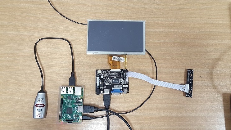
For the implementation of the interface, the Sainsmart 7" TFT touch screen display was used. This screen uses a driver board that is able to accept HDMI, VGA and AV inputs. The Raspberry Pi 2 has a built in HDMI, so this was used as the video output.
Objective 3; Reimplementing RF System
RF Design
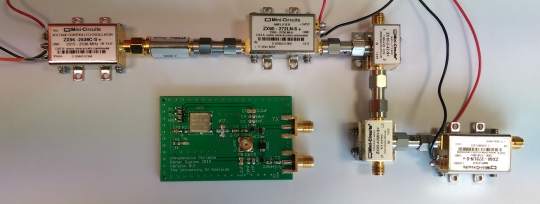
The MIT RF system consists of SMA connected components in a simple design which is easy to manufacture, has few areas of additional interference or noise, and can individually test each component. However, this system is large and costly. To achieve this objective it was decided to implement the RF system onto a PCB. The miniaturization of the RF system from these SMA connected components onto a PCB would reduce the size and cost of this system. The two designs can be seen in Figure 9. The PCB design does introduce many additional factors which can effect the performance of the system. The PCB architecture is based on that of the MIT design with appropriate SMD's replacing their counterpart SMA components.
The design of an analog PCB is critical as there are many factors that can effect the signal in the circuits transmission line. Generally, the circuit will be attempting to amplify and use one particular signal while rejecting all others including any noise present. This section will discuss the design rules, guidelines and optimization techniques used to design and implement a successful PCB circuit. It defines key characteristics and is then broken down into key areas and the design considerations that apply to them.
RF Testing
The RF system produced accurate results when tested with a cable, thus it was integrated with last years Honours system for full system testing. This included using the antennas. The power was supplied by a bench top power supply thus the testing had to be performed in the Honours labs.
- Range Mode Testing
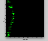
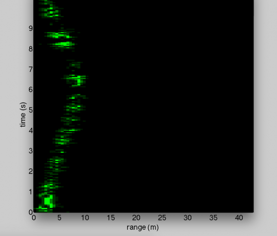
The Range mode results are shown below. The green line in these graphs indicates the distance the target is from the radar.
- Doppler Mode Testing
The Doppler mode results are shown below. The red in the graph indicates the speed of the target.
RF Redesign
As the key challenges posed to us throughout the project were due to our lack of knowl- edge and experience. when the project went on, our skills improved and the challenges became less of an issue. This allowed us to continuously improve the RF system through the design stage, and achieve more accurate and relevant results in testing. Upon evaluating our designs towards the end of the project, we were able to identify several key areas which could easily be improved. Such areas include adding bandpass filters into the system to reduce the interference of sidebands and noise as some of these sidebands harmonics and noise are not in range of Wi-Fi band. Also switching a few components for better models to improve important characteristics such as VSWR and IOP3.
Conclusion
The tests undertaken on the RF system alone did not provide conclusive data to indicate that the system worked as expected. This may be due to the fact that tests using the signal generator were inconsistent due to the fluctuating VCO frequency, and the tests including the cable were compared against approximate values. When the video amplifier and antennas were incorporated into the testing, the video amplifier initially worked as expected however the antennas introduced a large amount of noise (likely due to the crowded lab environment). When the RF system was integrated with the old video amplifier and the signal was processed and displayed, clear and accurate results were produced. In comparison to the the 2014 Honours radar the results produced were either the same or better.
Objective 4; Reimplementing Power Source
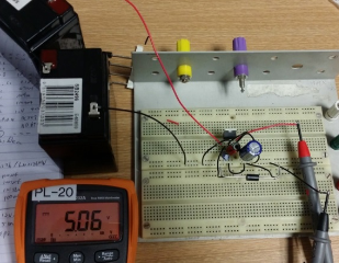
DC to DC converter is very important in portable electronic device. Switched DC to DC converters can get the required voltage and it could save space instead of using more batteries. There are two main types of converters: such as step-down, step-up. Step down like buck converter, when the input voltage is higher than the output voltage. Step up like boost converter, when the input voltage is lower than the output voltage. The switch mode converter increases the running time of the battery operated the devices, and also reduces the size of the heatsink. The heat sink is not necessary in some cases. The linear regulator can provide a low noise output voltage which is very good for radio frequency circuit.
The input voltage is two 6 volts battery. To convert 12 V to 5V, the three terminal linear regulators are very popular which the 2014'd final year project group used in their design. LM2576 series simple switcher step-down voltage regulator has been used in this year’s design, because 3 terminal need larger heat sink and LM2576 didn't require any heat sink in some cases. The benefit of the LM2576 is requiring a min number of components and these regulators are simple to use.
Implement All in One PCB
All in one PCB could make the radar system smaller. "Power source, Video Amplifier"
video Amplifer testing: Gain(dB) VS frequency(Hz)
Objective 5; Implementing Radar Scanning
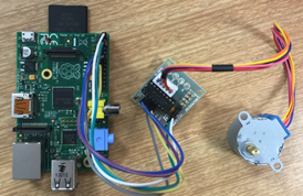
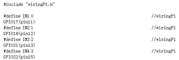
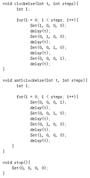
This is a new function for this project. The 28BYJ-48 with ULN2003 driver has been selected because it is the cheapest. Then install the Wringpi file for the GPIO, because the stepper motor is controlled by raspberry pi and connect to GPIO. The most important part is programming.
Project Outcomes
Even though this project faced many challenges and set backs, overall it has accomplished the aims which were set out, exceeding these in some areas by introducing the theory required to improve the radars characteristics. This project has also accomplished in greatly improving the depth of RF engineering knowledge, PCB design and testing, and general project management of team members. If this project is continued next year there are many areas which can be improved upon, however this years project team has definitely moved the project forward towards the future goal of this radar being used as a teaching tool.
Results
Doppler Mode
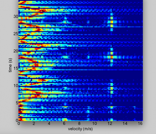
The Doppler mode is used to determine the velocity of a target in relation to the radar. To achieve this the Doppler Effect is used. The Doppler Effect is the change of the transmitted waves frequency due to a moving target. The output of the Doppler mode is shown in Figure 3. This figure represents a target increasing its speed to 3m/s, slowing to a stop and then repeating this process.
Range Mode
The Range mode is used to determine the distance a target is from the radar. To accomplish this a linear FM chirp needs to be transmitted. The reflected wave is received a short time after transmission, and as the transmitted wave is a chirp the received wave will be at a slightly different frequency. This frequency difference is used to calculate the targets range. The output of the Range mode is shown in Figure 4. This figure represents a target moving from in front of the radar to a range of 10m away and back.
Conclusion
This project faced many challenges and set backs, overall it has accomplished the aims which were set out, exceeding these in some areas by introducing the theory required to improve the radars characteristics. This project has also accomplished in greatly improving the depth of RF engineering knowledge, PCB design and testing, and general project management of team members. If this project is continued next year there are many areas which can be improved upon, however this years project team has definitely moved the project forward towards the future goal of this radar being used as a teaching tool.
Future Work
- Integrating all modules into one PCB
- Using different band e.g. 5GHz
- Improve output Graphs
Project Team
Student Members
- Mohammad Hasan:
Bachelor of Engineering (Honours)(Telecommunications)
- Kieren Nelson:
Bachelor of Engineering (Honours)(Electrical and Electronic)
- Angus Reid:
Bachelor of Engineering (Honours)(Electrical and Electronic)
with Bachelor of Mathematical and Computer Science
- Wenkai (Kelvin) Zhu:
Bachelor of Engineering (Honours)(Electrical and Electronic)
Academic Supervisors
- Dr Brian Ng
- Dr Hong Gunn Chew
References
[1] G. Charvat, J. Williams, A. Fenn, S. Kogon, and J. Herd, ”Build a Small Radar System Capable of Sensing Range, Doppler, and SyntheGc Aperture Radar Imaging,” Open Course Ware, Apr. 2011. [Online]. Available: hNp://ocw.mit.edu/ resources/. [Ac- cessed: Apr. 15, 2015].
