Difference between revisions of "Projects:2018s1-190 Dynamical Modelling of Synchronous Machines"
| Line 1: | Line 1: | ||
| + | == Project Name == | ||
| − | + | Dynamical Modelling of Synchronous Machines | |
| − | |||
| − | + | == Supervisors == | |
Andrew Allison, David Vowles | Andrew Allison, David Vowles | ||
| − | + | ||
| + | == Students == | ||
Lanbo Song, Qingyu Zhu, Xiaoyu Wang | Lanbo Song, Qingyu Zhu, Xiaoyu Wang | ||
| Line 16: | Line 17: | ||
| − | + | == Description == | |
This project aims to carry out a rigorous sequence of tests to measure the dynamical parameters of a synchronous machine. An important aspect of this project is the ability to capture and collate high-quality sets of measurements, and to combine these in order to estimate parameters. The other important aspect of the project is to model the synchronous machine (and prime-mover) to be able to predict experimental outcomes. | This project aims to carry out a rigorous sequence of tests to measure the dynamical parameters of a synchronous machine. An important aspect of this project is the ability to capture and collate high-quality sets of measurements, and to combine these in order to estimate parameters. The other important aspect of the project is to model the synchronous machine (and prime-mover) to be able to predict experimental outcomes. | ||
| Line 22: | Line 23: | ||
| − | + | == Background == | |
This project has been using the workstation 3 in the lab NG06. As shown in figure below, it is the basic part of workstation. The blue one is the DC machine, the yellow one is the induction machine, and the red one is the synchronous machine. | This project has been using the workstation 3 in the lab NG06. As shown in figure below, it is the basic part of workstation. The blue one is the DC machine, the yellow one is the induction machine, and the red one is the synchronous machine. | ||
| Line 33: | Line 34: | ||
As shown in the figure below, it is a cross-sectional schematic diagram of a three-phase synchronous machine with one pair of field-poles. The armature and the field are the two main elements. The field winding is supplied with direct current and produces a magnetic field which, due to relative motion between the armature and the field, induces alternating voltages in the armature windings. | As shown in the figure below, it is a cross-sectional schematic diagram of a three-phase synchronous machine with one pair of field-poles. The armature and the field are the two main elements. The field winding is supplied with direct current and produces a magnetic field which, due to relative motion between the armature and the field, induces alternating voltages in the armature windings. | ||
| − | + | [[File:Axis.jpg]] | |
| + | |||
Normally, the three armature windings are mounted on the stator (i.e. the stationary part of the machine) and the field winding is wound on the rotor of the machine. The three-phase windings of the armature are distributed 120 degree apart in space. Consequently, with uniform rotation of the magnetic-field produced by the field-winding, the three phase-voltages will be separated by 120 degree in time phase. | Normally, the three armature windings are mounted on the stator (i.e. the stationary part of the machine) and the field winding is wound on the rotor of the machine. The three-phase windings of the armature are distributed 120 degree apart in space. Consequently, with uniform rotation of the magnetic-field produced by the field-winding, the three phase-voltages will be separated by 120 degree in time phase. | ||
| Line 40: | Line 42: | ||
[[File:Data Acquisition Unit.jpg]] | [[File:Data Acquisition Unit.jpg]] | ||
| + | |||
The main function of the DAQ board is to collect, filter and transfer the data to the LabVIEW software. This device has multiple channels that can be used to get and transmit the data. The NI-6241 board has 8 differential and 16 single ended channels, the sample rate is 500kS/s. there are two analogue output channels and eight digital output channels. The output data can be either analogue or digital, then it will be transferred to the computer through a plug-in slot. | The main function of the DAQ board is to collect, filter and transfer the data to the LabVIEW software. This device has multiple channels that can be used to get and transmit the data. The NI-6241 board has 8 differential and 16 single ended channels, the sample rate is 500kS/s. there are two analogue output channels and eight digital output channels. The output data can be either analogue or digital, then it will be transferred to the computer through a plug-in slot. | ||
| Line 47: | Line 50: | ||
| − | + | == Objectives == | |
•Collect and collate high-quality measurements. | •Collect and collate high-quality measurements. | ||
| Line 55: | Line 58: | ||
| − | + | == Data Acquisition & Process == | |
Zero crossing detection generates triggering signals to obtain a set of data. The data are then used by Fourier Integration to estimate the mathematical expressions of the three-phase voltages and currents. | Zero crossing detection generates triggering signals to obtain a set of data. The data are then used by Fourier Integration to estimate the mathematical expressions of the three-phase voltages and currents. | ||
| Line 73: | Line 76: | ||
| − | + | == LabVIEW Realization == | |
Users can select different taps to acquire different information. | Users can select different taps to acquire different information. | ||
The diagrams below shows the LabVIEW interface and the capacity graph. | The diagrams below shows the LabVIEW interface and the capacity graph. | ||
| + | |||
[[File:LabVIEW Realisation 1.jpg ]] | [[File:LabVIEW Realisation 1.jpg ]] | ||
| + | |||
[[File:LabVIEW Realisation 2.jpg ]] | [[File:LabVIEW Realisation 2.jpg ]] | ||
Latest revision as of 20:30, 19 October 2018
Contents
Project Name
Dynamical Modelling of Synchronous Machines
Supervisors
Andrew Allison, David Vowles
Students
Lanbo Song, Qingyu Zhu, Xiaoyu Wang
Description
This project aims to carry out a rigorous sequence of tests to measure the dynamical parameters of a synchronous machine. An important aspect of this project is the ability to capture and collate high-quality sets of measurements, and to combine these in order to estimate parameters. The other important aspect of the project is to model the synchronous machine (and prime-mover) to be able to predict experimental outcomes.
Background
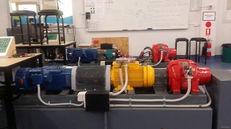
This project has been using the workstation 3 in the lab NG06. As shown in figure below, it is the basic part of workstation. The blue one is the DC machine, the yellow one is the induction machine, and the red one is the synchronous machine.
A synchronous electric motor is an AC motor in which, at steady state, the rotation of the shaft is synchronized with the frequency of the supply current; the rotation period is exactly equal to an integral number of AC cycles. Synchronous motors contain multi phase AC electromagnets on the stator of the motor that create a magnetic field which rotates in time with the oscillations of the line current. The rotor with permanent magnets or electromagnets turns in step with the stator field at the same rate and as a result, provides the second synchronized rotating magnet field of any AC motor. A synchronous motor is termed doubly fed if it is supplied with independently excited multi phase AC electromagnets on both the rotor and stator.
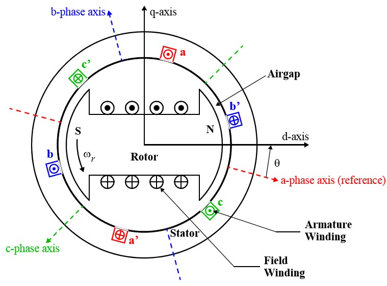
As shown in the figure below, it is a cross-sectional schematic diagram of a three-phase synchronous machine with one pair of field-poles. The armature and the field are the two main elements. The field winding is supplied with direct current and produces a magnetic field which, due to relative motion between the armature and the field, induces alternating voltages in the armature windings.
Normally, the three armature windings are mounted on the stator (i.e. the stationary part of the machine) and the field winding is wound on the rotor of the machine. The three-phase windings of the armature are distributed 120 degree apart in space. Consequently, with uniform rotation of the magnetic-field produced by the field-winding, the three phase-voltages will be separated by 120 degree in time phase.
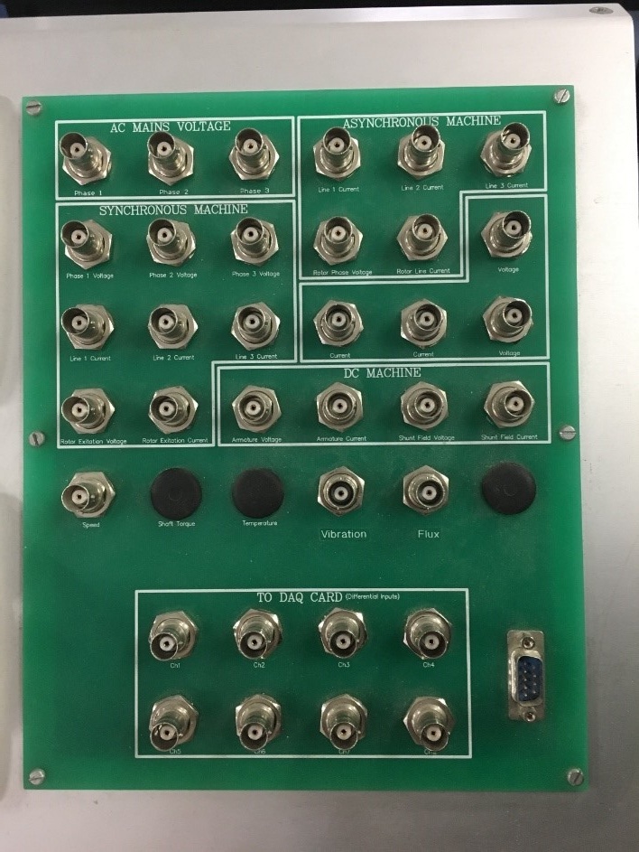
The Data Acquisition (DAQ) Board that has been used in lab NG06 is the NI-6341. The DAQ system mainly consists of the sensors, data acquisition unit, and a computer with the programmable LabVIEW software.
The main function of the DAQ board is to collect, filter and transfer the data to the LabVIEW software. This device has multiple channels that can be used to get and transmit the data. The NI-6241 board has 8 differential and 16 single ended channels, the sample rate is 500kS/s. there are two analogue output channels and eight digital output channels. The output data can be either analogue or digital, then it will be transferred to the computer through a plug-in slot.
In lab NG06, the software used to process the data is the LabVIEW. And a dynamical model of synchronous machines is able to display and predict the machine performance and is beneficial for engineers to operate the machines.
Objectives
•Collect and collate high-quality measurements.
•Establish quasi-real-time display of the machine performance via LabVIEW.
Data Acquisition & Process
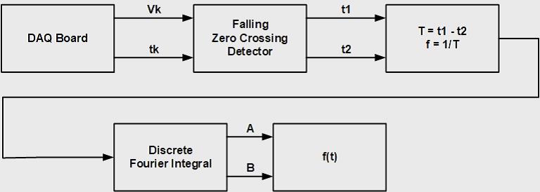
Zero crossing detection generates triggering signals to obtain a set of data. The data are then used by Fourier Integration to estimate the mathematical expressions of the three-phase voltages and currents.
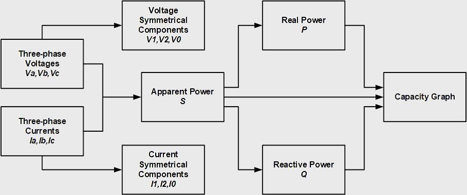
The three-phase voltages and currents gathered from the synchronous machine will be transferred into voltage symmetrical components and current symmetrical components, then the apparent power S will be generated. After finding the values for the real power P and reactive power Q, the capacity graph can be plotted.
This project also employs an encoding wheel and an incremental encoder interface programmed via LabVIEW to determine the absolute value of the rotor angle, in quasi-real-time.
LabVIEW Realization
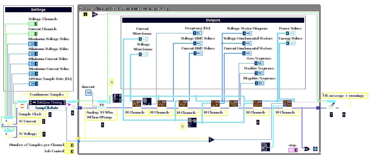
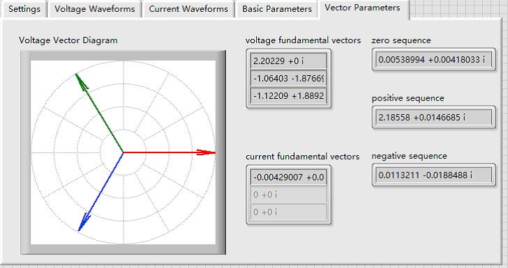
Users can select different taps to acquire different information.
The diagrams below shows the LabVIEW interface and the capacity graph.
