Difference between revisions of "Projects:2019s2-20001 Using Machine Learning to Determine Deposit Height and Defects for Wire + Arc Additive Manufacture (3D printing)"
(→Result discussion) |
|||
| Line 169: | Line 169: | ||
== Result discussion == | == Result discussion == | ||
These results show that there is a strong possibility of defect detection and CTWD prediction in welding. However, these initial findings are still a proof of concept. In the next stage of our research, we will refine the algorithm and integrate into AML's pipeline. | These results show that there is a strong possibility of defect detection and CTWD prediction in welding. However, these initial findings are still a proof of concept. In the next stage of our research, we will refine the algorithm and integrate into AML's pipeline. | ||
| − | |||
| − | |||
| − | |||
| − | |||
== References == | == References == | ||
<references /> | <references /> | ||
Revision as of 15:01, 15 October 2019
Contents
Introduction
AML3D is one of the leading company in the Wire Arc Additive Manufacturing (WAAM) industry. In short, WAAM is the Metal 3D printing. The technology has the ability to reduce up to 75% of manufacture time, cost, and material. Currently, WAAM is benefiting other industry such as: mining, defence, marine, and aviation.
Project team
Project students
- Anh Tran
- Nhat Nguyen
Supervisors
- Dr. Brian Ng
- Dr. Paul Colegrove (AML3D, sponsored company)
Objectives
The objective of this project is to increase the efficiency of the manufacture process at AML3D. In order to do so, the team will investigate into the possibility of automating and optimising the quality control processes. The two quality control processes that are currently being implemented at AML3D are measuring layer height using laser sensors, and human supervision for detecting defects. These processes add overhead into production time and usage of human resource, which is not desired. To achieve the goal, machine learning methods will be used extensively to analyse the electrical signatures of the weld process.
Background
Wire Arc Additive Manufacturing
Wire and Arc Additive Manufacturing (WAAM) is a type of additive manufacturing that uses electric arc as the heat source and material wire to feed the manufacture process [1]. WAAM has been investigated since the 1990s [1], but only recently that it received more attention from the manufacture world.
Its significant comes from the ability to manufacture complex model with less time and less material. Figure 1a and 1b show real parts that was manufactured by AML3D. Such custom made parts might takes months before be ready to be shipped, but with WAAM, the production time can reduce down to weeks. Currently, the industries that benefit the most from WAAM are maritime and aerospace.
Similar to other additive manufacture methods, WAAM achieves such results by sliding the models into multiple layers, and then build the model layer by layer. The movement control is normally handled by a robotic arm (AML3D uses ABB's Arc Welder robot), and the welding path is generated by a Computer Aid Manufacture (CAM) software.
Gas metal arc welding
-
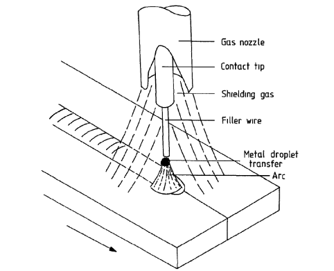 Figure 5: GMAW welding process [2]
Gas metal arc welding (GMAW), or also known as metal inert gas (MIG), is the welding process used at AML3D for WAAM. Due to its high deposition rate and economic benefits, GMAW has became more popular. We will explore two variants of GMAW, which are Pulse Multi Control and Cold Metal Transfer. Both processes are developed by Fronius, an Austrian welding company. Note that it is not required to understand the welding physics to follow this wiki. The next two following sections' purpose is to highlight the high variability, high dynamic nature in welding.
Pulse Multi Control
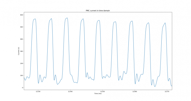
Pulse Multi Control (PMC) welding is Fronius' modified Pulsed GMAW. The advantage of Pulsed GMAW is the ability to control the metal droplet transfer in welding. Note that from figure 7, the metal droplet is characterised by a downward slope of the current pulse. Figure 8 shows the current signal captured from experiments conducted at AML3D (PMC is used).
-
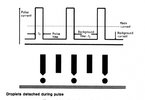 Figure 7: Relationship between pulse current and droplet transfer[2]
Cold Metal Transfer
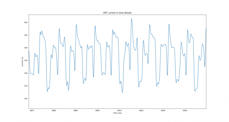
Cold Metal Transfer (CMT) is a complex welding process, also developed by Fronius. By detecting a short circuit (mode C and D in figure 9), CMT can make adjustment such as retracting the welding material to cool down, and therefore create a smoother, more stable weld. The complexity of CMT can be seen in the current signal of the process (figure 10). Compare to PMC, CMT's signal has more variation during one signal period.
Machine Learning
Machine learning (or statistical learning) refer to a set of tools to give data scientists an insight into the data and make better decisions based on those information [3]. In this project, we will explore the capabilities of classical machine learning methods (i.e anything but Deep Learning) due to the limitation of our available data. By the time of writing this wiki, we have only explored Support Vector Machine.
Support Vector Machine
The main idea of Support Vector Machine (SVM) is to draw hyperplanes that best separate multiple classes of data. The original SVM judges best decision hyperplane based on the separation margin between data classes (figure 11). However, there are multiple variants of SVM, such as hard/soft margin SVM, Nu-SVM, One class SVM (to solve anomaly detection problem). In our project, we choose to use a soft margin implementation of SVM. The benefit of soft margin SVM (as oppose to hard margin SVM) is that by allowing some misclassifications, we get a wider margin and therefore the solution becomes more "generalise" (i.e work better with a new set of dataset that is independent from the training dataset).
-
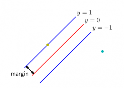 Figure 11: Separation margin [4]
Kernel tricks
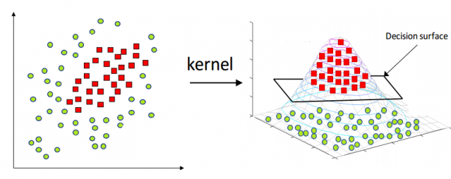
Both figure 11 and 12 are of linearly separable cases for SVM. For dataset that is not easy to separate with a hyperplane in their original features space (such as figure 13), the data often get projected into a higher dimension space where it is easier to separate (figure 14). Such technique is called the Kernel Tricks. It is important to note that Kernel Tricks does not actually "map" the data from X dimension to Z dimension, but rather pairwise compare the similarity of the input space in Z dimension.
-
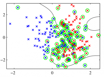 Figure 13: Nonseparable dataset [4]
Previous studies
There are many researches into defect detection in GMAW process. The three most dominant analysis methods are spectroscopic analysis, acoustic analysis, and electrical signal analysis.
Spectroscopic analysis
In [5], the authors captured the intensity of radiation emission of electric arc. It is obvious from figure 15 that good weld's intensity stays stable while defect one's is characterised by a sudden peak. Therefore, a threshold is set to detect the defect welds.
-
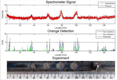 Figure 15: Spectroscopic analysis [5]
Other research into using spectroscopic data to monitor that can be of interest is [6].
Acoustic analysis
With [7], the author discovered that arc ignition is characterised by a distinct sound and therefore it is possible to capture the frequency of ignition through acoustic sensors. A tolerance band was set and both ignition frequency and sound pressure level were used to monitor the quality of the weld.
-
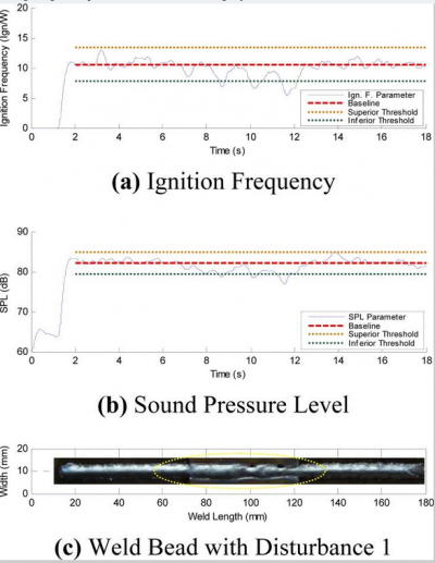 Figure 16: Acoustic analysis [7]
Other research into using acoustic signal to monitor that can be of interest are [8], [9].
Electrical signal analysis
With [10], the author plot the probability density distribution of voltage signal and discovered that the stable weld's signal concentrate in one region while unstable signal spread out. While in the paper, the authors did not developed a monitoring method using their findings, it shows that there is a significant differences between stable and unstable weld's electrical signature.
-
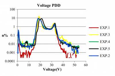 Figure 17: Voltage PDD [10]
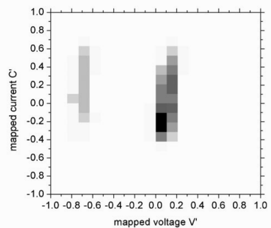
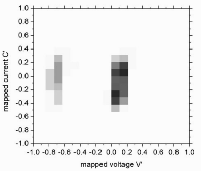
In [11], the authors shows that by plotting the signature image of voltage and current scatter plot, both arcing and short-circuiting region's signature image can notify a defects welds. A more visual representation of short circuiting and arcing region can be found in Gas metal arc welding section.
Other research into using electrical signal to monitor that can be of interest are [12], [13],[14],[15], and [16].
Experiment setup
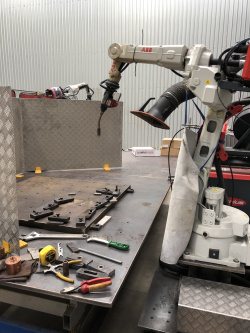
The welding system uses TPS 320i C Pulse (figure 15a), produced by Fronius, to supply power, feed wire, and system cooling. For movement control of the welding torch, the system use ABB’s IRB 1520ID (figure 15b), which is a dedicated arc welding robot. The Data Acquisition device is NI's DAQ. Each channel (voltage and current) is sampled at 25kHz while the dominant frequency for voltage and current signal are around 130Hz (for CMT process) and 190Hz (for PMC process).
Statistical Analysis
Preprocessing
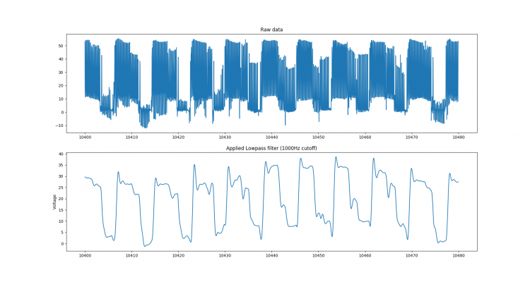
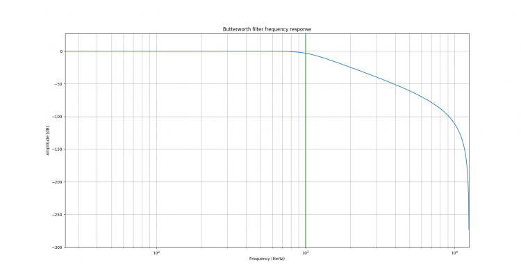
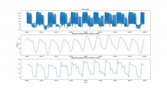
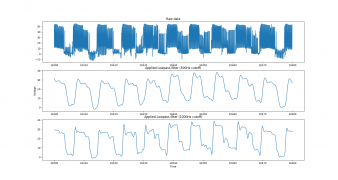
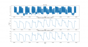
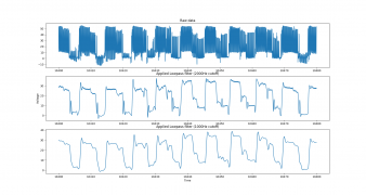
As the captured signal coming from Fronius' power supply, the signals also pick up switching power noise. The noise will interfere with the accuracy of the analysis if not filtered. In this project, we applied a 1000Hz digital Low Pass Butterworth filter. The effect of the filter can be seen in figure 20, while the comparation of using different filters can be seen in the gallery.
- Gallery: Comparison of different filtering method
Power Spectral Density
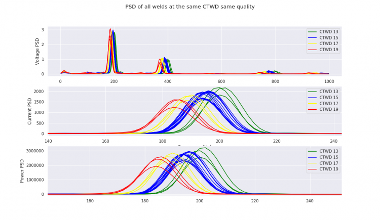
Our goal for this project is to detect the defect welds and predict the layer heights (the contact tip to work piece distance, CTWD, to be more accurate) in real time (refer to this section to understand the relationship between Contact Tip to Work-piece Distance and Layer height). An analysis of the current power spectral density (PSD) shows that there is an inverse proportional relationship between the CTWD of a weld and the frequency where its current signal PSD reach the peak, and also the magnitude of the peak. Since the peak of PSD can be fairly sensitive, we only consider the frequency of the peak PSD.
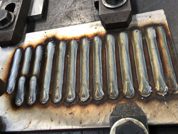
Figure 22 shows the PSD plot of voltage, current, and power signal of the weld using PMC process. In this experiment, we created multiple one-line, 8 seconds welds. These eight-second welds then get segmented into smaller two-second chunk to increase the number of data and decrease the processing time.
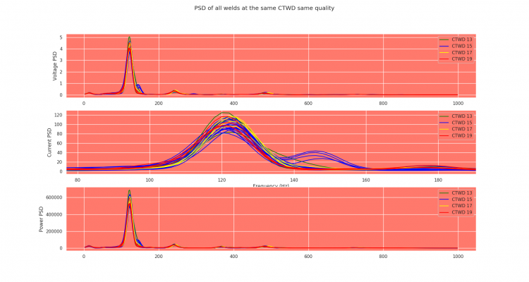
It seems like the inverse proportional relationship holds true for most cases. Other experiments showed that for a short period at the beginning and ending of the weld, the signal can behave differently relative to the rest of the weld. Currently, to migrate with this problem, data will not be collected and analysed (both offline and online) at these periods. However, the above results seem to only hold true for PMC processes. With CMT process, the current PSD plot indicates no relationship between the CTWD and the frequency at peak (figure 24).
For the next stage of the project, our plan is to develop a linear regression model to predict the CTWD for PMC process. With CMT process, we will have to look into different analysis techniques.
Support Vector Machine
By looking at the average voltage and average current of each segment of weld while making a simple straight path (PMC process), we realised there is a visible separation margin between stable and unstable welds. Using SVM with RBF kernel, we were able to correctly classify the quality of the weld with accuracy of 98%.
However, with CMT process, the separation cannot be observed.
CTWD Regression
With CTWD prediction, the result will only be useful if it is done on-the-line while making the part. And therefore, as oppose to defect detection, we cannot have a short calibration process every constant time to check for worn contact tip. By analysing the data while building a real part, we found that the average voltage (for PMC process) and average current (for CMT process) seems to have the strongest linear relationship with the CTWD. The acceptable error for CTWD prediction is +/- 1 mm (according to AML3D requirement). For both PMC and CMT process, our root means square error is less than 1 (PMC: 0.68 and CMT: 0.83), which satisfied the requirement.
Result discussion
These results show that there is a strong possibility of defect detection and CTWD prediction in welding. However, these initial findings are still a proof of concept. In the next stage of our research, we will refine the algorithm and integrate into AML's pipeline.
References
- ↑ 1.0 1.1 S. W. Williams, F. Martina, A. C. Addison, J. Ding, G. Pardal & P. Colegrove (2016) Wire + Arc Additive Manufacturing, Materials Science and Technology, 32:7, 641-647, DOI: 10.1179/1743284715Y.0000000073
- ↑ 2.0 2.1 Norrish, J. (2006). Advanced welding processes. Elsevier.
- ↑ James, G., Witten, D., Hastie, T., & Tibshirani, R. (2013). An introduction to statistical learning (Vol. 112, p. 18). New York: Springer.
- ↑ 4.0 4.1 Bishop, C. M. (2006). Pattern recognition and machine learning. Springer.
- ↑ 5.0 5.1 D. Bebiano and S. Alfaro, “A weld defects detection system based on a spectrometer,” Sensors, vol. 9, no. 4, pp. 2851–2861, 2009.
- ↑ D. Naso, B. Turchiano, and P. Pantaleo, “A fuzzy-logic based optical sensor for online weld defect-detection,” IEEE transactions on Industrial Informatics, vol. 1, no. 4, pp. 259–273, 2005.
- ↑ 7.0 7.1 E. Cayo and S. C. Alfaro, “A non-intrusive GMA welding process quality monitoring system using acoustic sensing,” Sensors, vol. 9, no. 9, pp. 7150–7166, 2009.
- ↑ M. Fidali, “Detection of welding process instabilities using acoustic signals,” in International Congress on Technical Diagnostic, pp. 191–201, Springer, 2016.
- ↑ L. Zhang, A. C. Basantes-Defaz, D. Ozevin, and E. Indacochea, “Real-time monitoring of welding process using air-coupled ultrasonics and acoustic emission,” The International Journal of Advanced Manufacturing Technology, vol. 101, no. 5-8, pp. 1623–1634, 2019.
- ↑ 10.0 10.1 A. Sumesh, K. Rameshkumar, A. Raja, K. Mohandas, A. Santhakumari, and R. Shyambabu, “Establishing correlation between current and voltage signatures of the arc and weld defects in GMAW process,” Arabian Journal for Science and Engineering, vol. 42, no. 11, pp. 4649–4665, 2017.
- ↑ 11.0 11.1 11.2 S. Simpson, “Signature images for arc welding fault detection,” Science and Technology of Welding and Joining, vol. 12, no. 6, pp. 481–486, 2007.
- ↑ R. Madigan, “Arc sensing for defects in constant-voltage gas metal arc welding,” Welding Journal, vol. 78, pp. 322S–328S, 1999.
- ↑ Y. Huang, K. Wang, Z. Zhou, X. Zhou, and J. Fang, “Stability evaluation of short-circuiting gas metal arc welding based on ensemble empirical mode decomposition,” Measurement Science and Technology, vol. 28, no. 3, p. 035006, 2017.
- ↑ Z. Zhang, X. Chen, H. Chen, J. Zhong, and S. Chen, “Online welding quality monitoring based on feature extraction of arc voltage signal,” The International Journal of Advanced Manufacturing Technology, vol. 70, no. 9-12, pp. 1661–1671, 2014
- ↑ X. Li and S. Simpson, “Parametric approach to positional fault detection in short arc welding,” Science and Technology of welding and joining, vol. 14, no. 2, pp. 146–151, 2009.
- ↑ E. Wei, D. Farson, R. Richardson, and H. Ludewig, “Detection of weld surface porosity by statistical analysis of arc current in gas metal arc welding,” Journal of Manufacturing Processes, vol. 3, no. 1, pp. 50–59, 2001.

