Difference between revisions of "Projects:2019s2-25601 Phasor Measurement Unit: FPGA Implementation"
(→IIR Filter) |
(→IIR Filter) |
||
| Line 29: | Line 29: | ||
== IIR Filter == | == IIR Filter == | ||
| − | [[File:IIR block diagram.png|300px| | + | [[File:IIR block diagram.png|300px|thumb|right|Block diagram of a second order IIR filter]] |
This topic presents the development of the IIR filter towards the implementation of FPGA. | This topic presents the development of the IIR filter towards the implementation of FPGA. | ||
Revision as of 09:14, 9 June 2020
Phasor Measurement Unit(PMU) is essential in the power industry in order to maintain the stability of the power network. Thus a need for a PMU that has a very high precision is a must. This project will try to implement a Matlab algorithm that was created by Prof C.J Kikkert into FPGA
Contents
Introduction
Phasor Measurement Units (PMUs) are used by the power industry to measure Voltage, Phase, Frequency and Rate of Change of Frequency (RoCoF) of the power system. The IEEE standard requires these measurements to be available within 2 mains cycles (40 mS) of the waveform sampling time. These PMU’s are an integral part of keeping the power system stable by controlling circuit breakers and generator settings in a high level of renewable power supply grid. Implementing the PMU algorithm in an FPGA is required to ensure the speed of operation and reliability required for this critical instrumentation.During 2018, Dr. Kikkert used Matlab to develop an algorithm to perform the PMU calculations quicker and with better accuracy than is possible at present. Hardware to digitise the 3 phase mains voltages has just been completed by Thesis students. This project aims to implement the floating point Matlab algorithm as a fixed point algorithm on a DE10-Lite FPGA development board from Terasic, using VHDL or Verilog. The code to be produced is to read the data from the digital to analogue converters on the existing hardware, calculate the Voltage, Phase, Frequency and RoCoF and send this data to a computer to be displayed using existing Labview code.As a second priority task, for higher grades, the same FPGA board is to be used with an available GPS receiver and existing hardware to produce a GPS time stamp for the Voltage, Phase, Frequency and RoCoF data.
Project Group 25601
Project students
- Rui Yang
- Mohamad Hafiz Mohamad Rodzi
- Junwen Zheng
- Sayed Mohd Amir Shahirudin Sayed Sagar
Supervisors
- A/Prof. Cornelis Keith Kikkert
- Dr. Said Al-Sarawi
Objectives
This project aims to achieve goals as follow:
1. To produce a fully working Phasor Measurement Unit.
2. Implement floating point Matlab algorithm in FPGA.
3. Calculate Voltage ,Phase , Frequency and RoCoF with a GPS time stamp.
4. Meet the requirement of IEEE/IEC standards.
Background
IIR Filter
This topic presents the development of the IIR filter towards the implementation of FPGA. The algorithm of the filter is designed by Adjunct A/Prof. C.J. Kikkert in MATLAB that suited to implementation in an FPGA. The paper wrote by him proves that the filter utilise fewer resources compared to the reference Finite Impulse Response (FIR) in the IEC/IEEE standard 60255-118-1:2018 Part 118-1: Synchrophasor measurements for power systems. This section shows the VHDL routines designed in the Quartus Prime software based on the MATLAB algorithm. VHDL is a hardware description language used to program the FPGA board. The IIR filter will make use of the IEEE 754 floating-point standard. The operations are carried on mantissa, exponents, and sign components. This includes the routine to convert the filter coefficients from the algorithms in a signed floating-point format.
Literature Review
Agarwal, Verma, Tiwari et al. [6] only used the anti-aliasing filter in their PMU design. Ref [7] designing a virtual PMU to interact with the real-time simulators as a way emulating the large number of real-life PMUs. They used the anti-aliasing filter to filter out the voltage and current analog inputs before the computation begins. Ref [8] reports that their PMU design is using the window method of FIR filter. The performance of the filter is investigated based on out of band rejection, noise, and harmonic elimination. The sixth order IIR filter in this project satisfies all the IEC/IEEE standard limit at 48 Hz main frequency
Method
Timestamp:The timestamp is the process of displaying the dte and time on the hardware. Receiving a message containing a time stamp on the UART interface. Decode the received message in accordance with the NMEA-0183 protocol. Make a multiplexer to switch between the time stamp and the current date stamp. And also convert the data to code 7 of the segment indicator on the FPGA. Frequency Lock Loop(FLL): Locking a desired frequency using PID algorithm since the PID algorithm can compare the measured value with the desired value and out in automatic control. measure the frequency of the VCXO generator. Calculate the frequency error and determine the following DAC value using the PID algorithm. Transfer data to the DAC. 10Mhz Generator: There is a 20mhz crystal control voltage oscillator on the printed circuit board, a 10mhz is required to be measured from the BNC connector, therefore a division of 2 algorithm will be performed.
Results
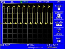
The result of 10 mhzs generation is shown below
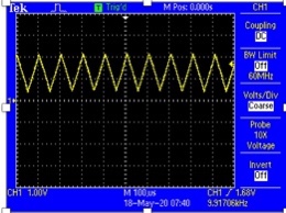
The result of DAC sawtooth waveform is shown below
The result of the FLL is shown below
The result of the time/date stamp are displayed below
Conclusion
The DAC sawtooth waveform, 10 Mhz desired frequency generation and the time/date stamp have been successfully achieved, however, the frequency lock loop was not locking for the 20 Mhz due to the harmonics interference. A smaller capacitor should be considered for C80 since C83 is 100 time bigger then the DAC waveform could be smoothed out and the triangular waveform could not be observe when the jumper is on pin 2 and 3 of JP1
References
[1] a, b, c, "Simple page", In Proceedings of the Conference of Simpleness, 2010.

