Difference between revisions of "Projects:2018s1-122 NI Autonomous Robotics Competition"
(→Robot Sensors) |
|||
| Line 29: | Line 29: | ||
The robot required a variety of sensors so that it may "see" track obstacles and boundaries and the surrounding environment. A variety of sensors were required so the robot could calculate its position and the positions of surrounding elements. | The robot required a variety of sensors so that it may "see" track obstacles and boundaries and the surrounding environment. A variety of sensors were required so the robot could calculate its position and the positions of surrounding elements. | ||
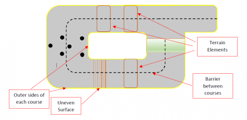
| − | [[File:Map.PNG| | + | [[File:Map.PNG|500px|left|Competition Track]] |
<!--[[File:Map.PNG]] --> | <!--[[File:Map.PNG]] --> | ||
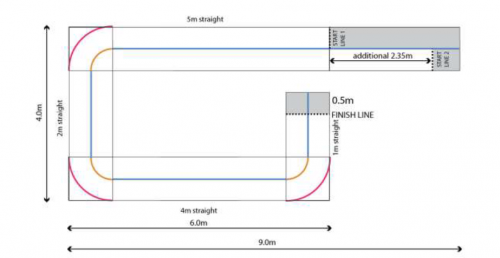
| − | [[File:MapDimensions.PNG| | + | [[File:MapDimensions.PNG|500px|left|Map Dimensions]] |
<!--[[File:MapDimensions.PNG]] --> | <!--[[File:MapDimensions.PNG]] --> | ||
| − | |||
The sensors used: | The sensors used: | ||
Revision as of 18:44, 17 October 2018
Contents
Supervisors
Dr Hong Gunn Chew
Dr Braden Phillips
Honours Students
Alexey Havrilenko
Bradley Thompson
Joseph Lawrie
Michael Prendergast
Project Description
Each year, National Instruments (NI) sponsors a competition to showcase the robotics capabilities of students by building autonomous robots using one of their reconfigurable processor and FPGA products. In 2018, the competition focuses on the theme 'Fast Track to the Future' where robots must perform various tasks on a track that incorporates various hazardous terrain, and unforeseen obstacles to be avoided autonomously. This project investigates the use of the NI MyRIO-1900 platform to achieve autonomous localisation, path planning, and environmental awareness, and autonomous decision making. The live final took place in September where university teams across Australia, New Zealand, and Asia competed against each other for the grand prize.
Processing Platform
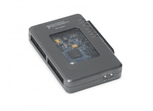
MyRIO - 1900 containing a dual core ARM processor and Xilinx Zynq FPGA.
Programming Environment
MyRIO processor and FPGA were programmed using LabVIEW 2017, a graphical programming environment. Additional LabVIEW modules were used to process the received sensor information, such as the 'Vision Development Module' and 'Control Design and Simulation Module'.
Robot Sensors
The robot required a variety of sensors so that it may "see" track obstacles and boundaries and the surrounding environment. A variety of sensors were required so the robot could calculate its position and the positions of surrounding elements.
The sensors used:
- Image sensor: Logitech C922 webcam
- Range sensors: ultrasonic & VL53LOX time of flight sensors
- Motor rotation sensors: motor encoders package
Image Sensor
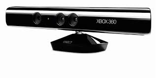
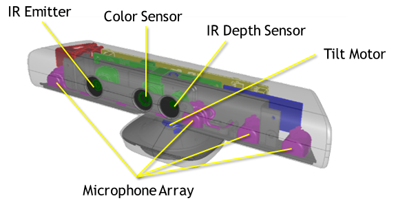
A camera is used as one of the various sensors for the purpose of determining accurate position and target location estimations. The Microsoft Xbox 360 Kinect Sensor USB 2.0 camera is an ideal candidate for the robot's vision because of it's capabilities, availability, and cost. This camera produces two types of images: RGB images and depth (range) images. The RGB images consist of three channels: red, green, and blue. The depth images are represented with one channel, with each pixel value representing the distance from the camera to the first obstruction encountered.
RGB Image Processing
The competition requires the robot to use the colour images for the following purposes:
- Identify boundaries on the floor that are marked with 50mm wide coloured tape
- Identify wall boundaries
Such processing will be taxing on the processor. Fortunately the myRIO contains an FPGA that can be used instead. This
The competition track boundaries are marked on the floor with 50mm wide coloured tape. The RGB images are processed to extract useful information. Before any image processing was attempted on the myRIO, the pipeline was determined using Matlab and its processing toolbox.
Determining Image Processing Pipeline in Matlab
An overview of the pipeline is as follows:
- Import/read captured RGB image
- Convert RGB (Red-Green-Blue) to HSV (Hue-Saturation-Value)
- The HSV representation of images allows us to easliy: isolate particular colours (Hue range), select colour intensity (Saturation range), and select brightness (Value range)
- Produce mask around desired colour
- Erode mask to reduce noise regions to nothing
- Dilate mask to return mask to original size
- Isolate edges of mask
- Calculate equations of the lines that run through the edges
The produced line equations can be converted to obstacle locations referenced to the robot. Path planning can make decisions based on locations and the robot can avoid them just as it would avoid obstacles.
