Difference between revisions of "Projects:2018s1-191 Quasi-Linear Circuit Theory"
(→Method) |
(→Method) |
||
| Line 41: | Line 41: | ||
| − | <br />c)Given a non-linear device, a linear operator H i.e. a transfer matrix [H] can by testing the device with | + | <br />c)Given a non-linear device, a linear operator H i.e. a transfer matrix [H] can determined by testing the device with a range of test signals. |
== '''Simulations''' == | == '''Simulations''' == | ||
Revision as of 14:59, 21 October 2018
Contents
Project Team
Students
- Yuan Yao a1674092
- Zizheng Ren a1680576
- Bruk Waldron a1645521
Supervisors
- Dr. Andrew Allison
- Prof. Derek Abbott
Introduction
As electrical power networks become more complicated, it becomes more important to analyse and control power quality. Harmonic is one of the most important aspect of power quality. Harmonics are defined as sinusoidal voltages or currents having frequencies that are integer multiples of the fundamental frequency in electric power system. Too much harmonic contents in power network will cause various problems such as excessive losses and heating in induction and synchronous machine, incorrect readings on meters and interference with other electronic devices and systems and so on. Some serious problems will lead to malfunction and even collapse of entire power system. Therefore, it is important for engineers to analyse and control harmonics for better power quality and normal operation of power system. One significant source of harmonics is the non-linear load. As non-linear loads create harmonics by drawing current in abrupt short pulses, rather than in a smooth sinusoidal manner. However, there is no suitable and sufficient circuit theory to model harmonics and their effect at the moment. As a result, the lack of theory has attracted our interest and inspired us to investigate this issue. We believe that the periodic analysis is one possible solution.
The aim of this project is to construct a complete and consistent circuit analysing theory to model non-linearity and effect of harmonics in electric circuits. To achieve this, the detailed periodic analysing method should be specified. A good notation to model circuit elements need to be determined. Simulation will be carried out using MATLAB and Simulink in terms of investigating the circuit response with non-linear load and non-sinusoidal signal. Finally, a complete theory will be proposed as described in project aim.
Background
Method
Proposed theory uses the complex Fourier series as a basis for performing circuit analysis. Proportion is to use the complex Fourier series as a type of domain i.e. similar to using the frequency or Laplace domain to performing circuit analysis. Hence it is an alternative to using traditional methods such as phasors.
Proposed Quasi Linear Circuit Theory;
a)Circuit sources are represented as vectors of complex numbers i.e. Vs(t) --> |Vs>
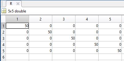
b)Circuit elements are represented as square matrices
    i.	Linear Circuit elements have matrices, where diagonals are the non-zero elements
       i.e. R --> [R] , jwL --> [jwL] ect.
ii. Non-Linear circuit elements have non-zero off-axis’s elements, but the diagonal elements are still dominant i.e. largest
c)Given a non-linear device, a linear operator H i.e. a transfer matrix [H] can determined by testing the device with a range of test signals.

