Difference between revisions of "Projects:2015s1-26 Autonomous robotics using NI MyRIO"
(→Project outcomes) |
(→Project outcomes) |
||
| Line 214: | Line 214: | ||
Localisation will require more refinement as its accuracy is not suitable for use. | Localisation will require more refinement as its accuracy is not suitable for use. | ||
| − | [[File:Good Run.gif]] | + | [[File:Good Run.gif]] [[File:Good Run.gif]] |
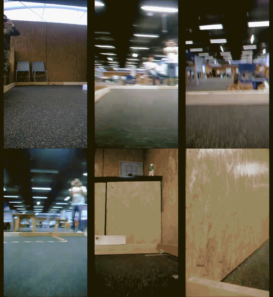
| − | video of ternimal 1 and 3 unloading test ( robot view ) | + | video of ternimal 1 and 3 unloading test ( robot view ) video of ternimal 1 and 3 unloading test ( observer view ) |
| − | |||
| − | |||
| − | |||
| − | video of ternimal 1 and 3 unloading test ( observer view ) | ||
== Recommendations and Future Work == | == Recommendations and Future Work == | ||
Revision as of 03:32, 23 October 2015
Contents
Introduction
This project proposed the construction of an autonomous robot designed around the National Instruments (NI) processing unit called myRIO. The robot was entered into the National Instruments Autonomous Robotics Competition (NIARC) and was designed to autonomously navigate an environment with obstacles, collect cargo and deliver cargo to target terminals. Areas of specific focus included obstacle avoidance, navigation and localisation. This project also made use of various project management skills to ensure the successful completion of the project. Overall, the team were able to meet all milestones and attended the finals at the University of New South Wales on the 22nd September 2015.
Supervisors
Dr Hong Gunn Chew
A/Prof Cheng-Chew Lim
Honours Students
Under Graduate Group:
Adam Mai
Adrian Mac
Song Chen
Post Graduate Group:
Bin Gao
Xin Liu
Yiyi Wang
Project Details
2.1. Aims and Objectives
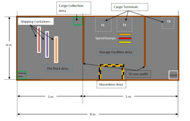
The aim of this project was to develop an autonomous robot using the National Instruments myRIO in addition with a graphical programming software called LabVIEW. The robot required intelligence in the fields of obstacle avoidance, navigation and pathfinding, localisation as well as object handling [14] in order to traverse the environment depicted in Figure 2.4.1. Implementations of these modules was divided amongst two groups: the under graduate group and post graduate group. The majority of the software responsibilities were carried out by the under graduates while the post graduates dealt with the mechanical aspects of the robot. In regards to the implementation, this project aimed to address three hypotheses:
1. The Kinect sensor with ultrasonic sensors or ultrasonic sensors alone can accomplish object avoidance.
2. The A* algorithm can be implemented in such a way that the robot can freely move in any direction.
3. Odometry used in conjunction with filters and sensors will be able to localise a robot accurately in a defined environment.
Furthermore, in order for the robot to precisely complete all required motions, the following was also required:
1. Proper Proportional, integral and differential (PID) control algorithm are required to control DC motors to drive the robot moving with high accuracy.
2. Adequate communication strategies between the navigation module and the robot driving module need to be developed.
3. A power supply module is needed to meet various voltage and current requirements of the robot.
4. A suitable mechanical structure should be developed according to competition task and rules specification and hardware requirements.
With a total budget of $2250, this project further aimed to minimise costs and produce a robot that is cost effective and reliable. The overall final product should be able to avoid both static and dynamic obstacles, determine its own route and transport goods to target locations. As this transportation process will be timed during the competition, maximising time efficiency will be important as well as ensuring the safety of the robot’s environment.
2.2. Significance of Competition
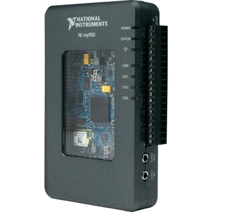
Figure 2.2.1: National Instruments myRIO unit
This project exhibits the capabilities of the National Instruments myRIO as well as the CompactRIO. The CompactRIO is a real-time embedded industrial controller which National Instruments offers to industries [15]. The myRIO has a similar purpose and acts as a light version of this controller for students to use for smaller applications [16]. In consequence, the competition markets these abilities for National Instruments while allowing students to work with robots. The project illustrates the potential of using autonomous robots as a means of cargo transportation in a shipyard. Similar to all the other previous competitions held by National Instruments, it ultimately displays the benefits of using autonomous robots for industrial applications. The world has seen the power of autonomous robotics within domestic households, where robotic vacuums such as the Roomba have become increasingly popular [2]. Although more primitive than the competition robots, the fundamental idea of portraying the power of autonomous robotics in industries is evident. Furthermore, displaying the skills of future engineers greatly emphasises what the world can expect in the field of robotics for the years to come.
2.3. Motivation for Competition
There are three fundamental motivations behind this project. Firstly, on a national scale, by allowing universities from around Australia and New Zealand to compete with each other, it allows aspiring students to apply themselves in the field of robotics. Consequently, it encourages growth and innovation within this field of work [1] as well as demonstrates the capabilities of this generation’s engineers. Secondly, being a competition funded by the university, the successful completion of the project will allow universities to showcase not only the capabilities of their students, but also their quality of education. Lastly, on a personal level, both post graduate and under graduate students will benefit from the knowledge and experience that are gained upon completion of the competition. It allows them to become familiar with the integration of different systems working in conjunction with each other as well as with project management processes. Ultimately, it allows students to grasp an understanding of the requirements of a professional engineer.
2.4. Introductory Background
Figure 2.4.1: Map of the National Instruments competition track (sourced from [14])
National Instruments (NI) is a company responsible for producing automated test equipment and virtual instrument software. Every year, it sponsors the National Instruments Autonomous Robotics Competition (NIARC) to allow tertiary students to challenge their capabilities in the robotics field. The theme of the competition changes annually and for 2015, the theme is “Transport and Roll-Out!” [1]. This theme simulates the use of an autonomous robot to collect and transport cargo in a shipyard. As such, this project will require the development of an autonomous robot in conjunction with National Instruments’ myRIO device. The following describes the procedure in which the robot will need to move in the competition. It has been sourced from the NIARC Task and Rules [14] and Figure 2.4.1 illustrates the overall course that will be traversed. Firstly, the robot will be required to navigate itself from the starting location to the cargo collection area. In between these zones will be a maximum of 3 static obstacles (shipping containers) which will need to be avoided by the robot. Once it reaches this collection area, a team member will simulate a crane and load the cargo on to the robot. After, the robot will unload cargo at any of the cargo terminals whilst avoiding any obstacles on its way. Here, the robot will need to deal with walls, speed bumps as well as a dynamically moving obstacle (another vehicle) in the hazardous area. Once it has no more cargo to unload, it will navigate itself to the finish area. The robot will have a three minute time limit to complete all these tasks.
2.5. Technical Background of Robot System
The autonomous robot system will utilise a range of techniques and components in order to implement its various features. The following is a list of the components, techniques and algorithms that will be used within this project. It also includes any relevant theories that apply to the robot system’s implementation.
myRIO: The myRIO is a processing unit developed by National Instruments. It consists of a dual core ARM Cortex A9 processor and a Xilinx FPGA (Field Programmable Gate Array) with a number of analogue and digital inputs and outputs that can be used. The main advantage of using this system is that it is able to acquire and process data in real time. Please refer to Appendix F for an image of the myRIO device.
LabVIEW: The majority of the software coding will carried out in a program called LabVIEW which is developed by National Instruments. LabVIEW is a graphical programming tool which places great emphasis on dataflow and allows for code to be executed in parallel. It makes use of many built in functions which allows for real time processing. In contrast to structured text programs which are written in text editors, LabVIEW has all its code programmed into a Virtual Instrument (VI). This acts in much the same way as the text editors which are used to write structured text programs.
Image/Ultrasonic/Infrared Sensors: The Xbox Kinect Sensor is an image sensor intended for use with the Xbox gaming console. It consists of a RGB (red-green-blue) camera and a pair of infrared optics sensors. It is able to track human movement and implements depth imaging by triangulation using its dual infrared sensors [4]. Ultrasonic sensors are range detection sensors which work by transmitting high frequency sounds. It calculates distance by measuring the time it takes for reflections to return to the sensor. It makes use of the speed of sound which is approximately 340 m/s at sea level, but this value can vary depending on conditions such as temperature and humidity. Infrared sensors are another form of range detection sensor that measures infrared light radiating from objects in its field of vision. It can also be used to detect colour and calculate the distance of objects. As it measures the intensity of the light it senses, other light sources can affect its overall reading such as sunlight.
Data Fusion: Data fusion is a theory and technique which is applied to a system in order to synthesise all its raw sensor data into a common form [12]. It makes use of certain conversion and transformation formulas into order to do this. Its implementation becomes particularly important when a system utilises multiple sensors and needs to translate all this information and make a decision. Data fusion ultimately gives the outputted values more significance as it improves the meaning of the data [12].
Path Planning and Path Following Algorithms: Path planning algorithms determine and plan paths that the robot can traverse through to reach a target destination. This includes the A* algorithm used to solve for the shortest path [10] as well as the local tangent bug algorithm which requires the direction of the target to operate [11]. These are to be used in conjunction with path following algorithms to allow the robot to move to a target point.
Pose: The pose of the robot refers to its position and orientation within an area [21]. It displays this information through coordinates (x, y) and through an angle (°) relative to the origin of a map (0, 0) in an anticlockwise direction.
Odometry: Odometry refers to the use of encoders to measure a robot’s wheel axes rotations such that information about its pose can be known [23].
Three-term closed loop control algorithms: The three-term control is also called proportional-integral-differential (PID) closed loop control. The application of this algorithm aims to balance and stabilise DC motors of the robot so that a good performance is obtained, which is the fundamental of the odometry-based robot pose finding.
Simultaneous Localisation and Mapping (SLAM) Algorithms: SLAM algorithms are used as a means to localise and map a robot’s surrounding area at the same time. It is generally used with visual systems to create 3D environment models [22].
Feature Extraction: Feature extraction refers to the classification of objects in an image by extracting specific features of this image and comparing them with a pattern classifier [21][25]. It allows a robot to distinguish the difference between a wall and an obstacle.
2.6. Project and Competition Constraints
Several project constraints have been set by National Instruments and the university that will affect the design and production of the autonomous robot. Firstly, the system must be designed to include the MyRIO as the main or only processing unit. Secondly, the majority of the programming must be accomplished in LabVIEW. Besides, The insufficient FPGA resources on MyRIO limits the choices of robot control strategies and requests a high code efficiency. There are also restrictions in budget, with a total of $2250 being provided to purchase all components and materials for prototype robot and full size competition course. Therefore, as the team aims to minimise project spending, component options will become more limited. The size of the robot is also constrained by the height of the cargo terminal housings as well as by the width of the taped areas [14]. Lastly, time is a large constraint in this project as missing milestones relating to the National Instruments competition will result in a forfeit. As such, this constraint will need to be addressed properly to ensure task dates are met.
Competition Requirements
The National Instruments Autonomous Robotics Competition (NIARC) require university teams to complete a number of requirements before they are permitted to go to the finals. The competition calls for the design of an efficient robot that will safely navigate in a ship yard environment [14]. The robot needs to be safe such that it does not cause any harm to its environment. In real world situations, it is very critical that technology is safe to use in its surrounding environment so that it does not cause injury to personnel. This competition required teams to develop and show through video that they are able to:
• Control a motor and sensor
• Demonstrate that their robot can avoid obstacles
• Demonstrate that their robot can navigate itself to a designated position whilst knowing where it is approximately located in the track (localisation)
• Demonstrate that their robot can hold on to cargo and unload them at designated positions
Deadlines for these demonstrations had to be met throughout the year and if any of these milestones were missed, the team would no longer be able to participate in the finals. In order to achieve these requirements, the robot required the following subsystems:
• Static/Dynamic Obstacle Avoidance subsystem
• Navigation and Localisation subsystem
• Path Planning subsystem
• Object Handling subsystem
It should also be noted that as a restriction placed on teams, the myRIO had to be the main processing unit and the majority of the software code had to be written in LabVIEW.
Competition Planning
3.1. Work Breakdown
This project requires the completion of two sets of tasks: university milestones and National Instruments milestones. The majority of university milestones follow a waterfall type structure where each deliverable builds upon the next. In contrast, the National Instruments milestones have more concurrency between milestones as there is little dependence between each deliverable. As such the approaches taken for each set of deliverables will be different. Tasks have been assigned to each member of both the under graduate group and post graduate group as follows:
Song Chen:
• Assist in implementation of obstacle avoidance
• Research and implement path smoothing for the robot
• Filter implementation for localisation
Adrian Mac:
• Implement obstacle avoidance for the robot system
• Assist in navigation and localisation
• Terminal and corner detection using Kinect
Adam Mai:
• Assist in implementation of obstacle avoidance
• Implementation of navigation using A* algorithm
• Colour detection using Kinect
Xin Liu:
• Implementation of three-term closed loop control of the robot driving system
• Implementation of the electrical driving control of the the unloading mechanism
• Implementation of the communication interface between the robot driving system and its navigation system
Bin Gao:
• Design and implementation of the robot power system
• Design and implementation of power distribution circuit to realise the separating power-up function
• Assist in Establishment of the full size competition course for the robot test
Yiyi Wang:
• Design and implementation of the robot mechanical structure
• Design and implementation of the unloading mechanism
• Establishment of the full size competition course for the robot test
3.2. Budget
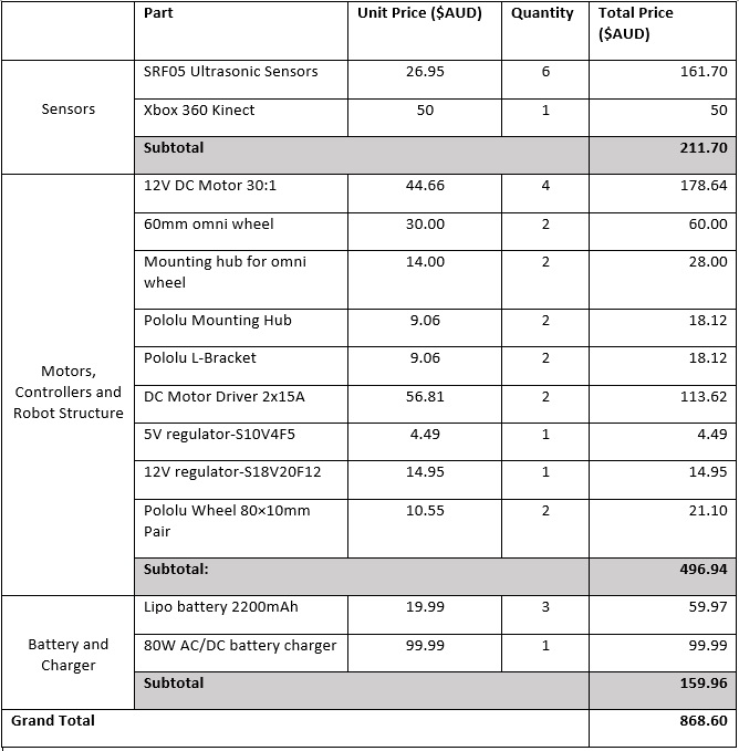
The total budget made available to the under graduate group was $750 with $250 being provided for every group member. In comparison, the post graduate group had a budget of $1500 with $500 being granted for each member. The total amount spent on robot was $869. However, this amount does not include costs for shipping, the myRIO device, the printed circuit boards and any 3D printed structures. The amount spent on the final robot can be viewed in the table below.
Deliverables and Milestones
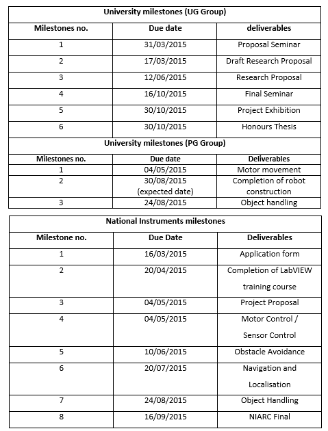
This project has two sets of milestones: one for the university and one for National Instruments. As the project requires the collaboration between the under graduate and post graduate groups, there will be two sets of milestone tables for the university. It was very important that the team met all the competition milestones as failing to meet any one would have resulted in a forfeit.
Project outcomes
The robot is able to move at a continuous top speed of 1m/s. It is able to complete a full run of the course while unloading in terminal one and three in 50 seconds and this includes a loading time of 6 seconds. The loading time could be improved on by creating a loading a mechanism rather than individually loading the cargo individually.
The robot is able to meet all requirements set by the competition however one limitation is that the robot is not programmed to traverse over the speed bumps. Test runs over the speed bumps were conducted and proved to be successful however concerns remained over the structural integrity of the motor shafts. The lack of a suspension system and a heavy chassis resulted in a decision to not traverse the speed bumps in any further runs.
Localisation will require more refinement as its accuracy is not suitable for use.
video of ternimal 1 and 3 unloading test ( robot view ) video of ternimal 1 and 3 unloading test ( observer view )
Recommendations and Future Work
One possible improvement which was unexplored is the use of an additional processor. The competition has no restrictions on the use of other processors except that the MyRIO must be the central processing unit and while it is flexible, it lacks computational power. The Monte Carlo Localisation is a proven technique but requires high processing power. It has been shown to localise a mobile robot in an area much larger than the competition track. A drawback is the increased cost of the addition of a processor.
Basic functions have been achieved with the Kinect in terms of navigation however methods such as 2D SLAM provides a more comprehensive solution to the spatial awareness of the robot. The visual mapping of the environment provides valuable insight on the sensory performance of the robot which provides useful insight into its decision making. One key limitation was the lack of knowledge and experience in image processing and this was compounded by the required use of LabVIEW. Future groups attempting this project should consist of at least one member with a working knowledge in image processing.
Following from this, the Kinect was mounted at a height above the track boundaries and was tilted 10 degrees towards the surface. This added complexity in processing the data obtained as it provides more information than desired as it is able to overlook boundaries and see objects further away. This is both an advantage and disadvantage. The extra information obtained can be used for better spatial recognition however it requires extra processing.
Data logging and internal monitoring of the system is a valuable tool for debugging. The movement commands and internal states of the robot was displayed but data logging was not implemented. It was a common occurrence that the robot was transitioning into the next state prematurely and without data logging, the high data throughput was not easily interpreted in finding the error. Such a technique would allow for a systematic approach in debugging and improve overall efficiency in the implementation and testing phases while providing valuable insight into the sensory readings.
Video and Resources
Submitted Milestone Videos for NIARC:
Motor Control: https://www.youtube.com/watch?v=FRvMSo38yPE
Sensor Control: https://www.youtube.com/watch?v=onqwc6NWYr4
Navigation and Localisation: https://www.youtube.com/watch?v=nOyzQ6HA9o4
Object Handling: https://www.youtube.com/watch?v=GP6bkqo2B7c
LabVIEW code: RT Main
References
[1] National Instruments 2015, NI Autonomous Robotics Competition 2015, National Instruments, viewed 15 April 2015, <http://australia.ni.com/ni-arc>.
[2] Tribelhorn, B & Dodds, Z 2007, "Evaluating the Roomba: A low-cost, ubiquitous platform for robotics research and education", paper presented to IEEE International Conference on Robotics and Automation, Roma, 10-14 April, viewed 14 April 2015.
[3] N. Ali, "Human Tracking and Robot Navigation using Multiple Sensors", University of Adelaide, Adelaide, SA, 2013.
[4] Z. Islam, "Robot Navigation using Multiple Depth Sensors", University of Adelaide, Adelaide, SA, 2013.
[5] Y. Pang and Y. Wang, "Autonomous Robot Navigation using a movable Kinect 3D sensor", University of Adelaide, Adelaide, SA, 2014.
[6] G. Csaba and Z.Vámossy, "Fuzzy Based Obstacle Avoidance for Mobil Robots with Kinect Sensor", in 4th IEEE International Symposium on Logistics and Industrial Informatics, Smolenice, Slovakia, 2012.
[7] P. Benavidez, "Mobile Robot Navigation and Target Tracking System", in 6th International Conference on System of Systems Engineering, Aluquerque, New Mexico, USA, 2011. pp. 299-304.
[8] D. Correa et al., "Mobile Robots Navigation in Indoor Environments Using Kinect Sensor", in Second Brazilian Conference on Critical Embedded Systems, 2012 © IEEE, doi: 10.1109, pp 36-41.
[9] J. Borenstein and Y Koren, "Real-Time Obstacle Avoidance for Fast Mobile Robots", IEEE Trans. Syst. Man Cybern. (1971–1995), vol. 19, no. 5, 1989, pp. 1179-1187.
[10] X. Cui and H. Shi, "A*-based Pathfinding in Modern Computer Games", Victoria University, Melbourne, Victoria, 2011.
[11] J. Ng, "An Analysis of Mobile Robot Navigation Algorithms in Unknown Environments", University of Western Australia, Perth, WA, 2010.
[12] H.B. Mitchell and M. Batya, “Common Representational Format,” in Data Fusion: Concepts and Ideas, 2nd ed. Berlin, Germany: Springer Berlin Heidelberg, 2012, pp. 51-52.
[13] A. Goshtasby, "Introduction", in Image Registration: Principles, Tools and Methods, 1st ed. Springer, London, England, 2012, Ch 1, pp. 1-3.
[14] National Instruments 2015, National Instruments Autonomous Robotics Competition: 2015 Competition Task and Rules, National Instruments, viewed 16 May 2015, <http://australia.ni.com/sites/default/files/NI%20ARC%202015%20Task%20and%20Rules%20Documentation_0.pdf>.
[15] National Instruments 2015, NI CompactRIO, National Instruments, viewed 15 April 2015, <http://www.ni.com/compactrio/>.
[16] National Instruments 2015, NI myRIO, National Instruments, viewed 16 April 2015, <http://www.ni.com/myrio/>.
[17] Cytron Technologies 2013, HC-SR04 User’s Manual, Cytron Technologies, viewed 3 May 2015, <https://docs.google.com/document/d/1Y-yZnNhMYy7rwhAgyL_pfa39RsB-x2qR4vP8saG73rE/edit>.
[18] Robot Electronics 2015, SRF05 – Ultra-Sonic Ranger, Robot Electronics, viewed 3 May 2015, < http://www.robot-electronics.co.uk/htm/srf05tech.htm>.
[19] MaxBotix 2014, LV-MaxSonar-EZ Series High Performance Sonar Range Finder, MaxBotix, viewed 3 May 2015, < http://maxbotix.com/documents/LV-MaxSonar-EZ_Datasheet.pdf>.
[20] N. Ganganath and H. Leung, “Mobile Robot Localisation using Odometry and Kinect Sensor,” in IEEE International Conference on Emerging Signal Processing Applications, Las Vegas, Nevada, 2012, pp. 91-94.
[21] X. Smith, “Robot Localisation, Navigation and Control using National Instruments myRIO,” Flinders University, Adelaide, SA, 2014.
[22] Y. Zou et al., “Indoor Localization and 3D Scene Reconstruction for Mobile Robots Using the Microsoft Kinect Sensor,” in IEEE International Conference on Industrial Informatics, Beijing, China, 2012, pp. 1182-1187.
[23] P. Jensfelt, “Approaches to Mobile Robot Localization in Indoor Environments,” Ph.D dissertation, Dept. Signals, Sensors and Systems, Royal Institute of Technology, Stockholm, Sweden, 2001.
[24] M. Likehachev et al., “Anytime Dynamic A*: An Anytime, Replanning Algorithm,” Carnegie Mellon University, Pittsburgh, USA, 2005.
[25] F. Shih, “Feature Extraction,” in Image Processing and Pattern Recognition, 1st ed. John Wiley and Sons, New Jersey, USA, 2010, Ch. 8, pp. 269-305.
