Projects:2014S1-01 Development of Fully Automated Educational and Training Tool for Wind and Solar Energy using National Instruments’ ELVIS Based System
Contents
Project Overview
Project Motivation
Renewable energy is a fast growing industry. Training systems which are simple to operate, relatively easy to understand and cost effective will be vital in teaching those who move into this industry.
The current Distributed Generation Technologies (DGT) practical can be difficult to set up, and requires at least two multimeters and an oscilloscope to take measurements. It also only uses non-illuminated tests of the solar panel, which are not as accurate as illuminated characteristics. The experiment does not incorporate accurate sensor values to identify the relationship between environmental conditions and the characteristics of the generator. Commercially available options, such as the EMONA HELEX board [1], are very expensive and offer limited functionality. The university is in possession of an ELVIS system that allows for the development of circuit boards that can be directly connected to a 16 channel ADC and other useful digital and analogue outputs and inputs. An improved version of the EMONA board would be a great way to utilise this equipment to improve student learning through practical experience.
Project Introduction
The main aim of this project is to develop an automated education and training tool for wind and solar energy using National Instruments’ ELVIS platform, initially for use in student practicals. The current distributed generation practicals can be difficult to perform, both in wiring correctly and getting accurate measurements. Commercially available alternatives are prohibitively expensive and have limited features.
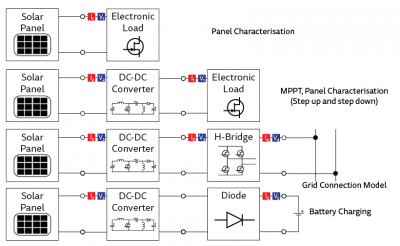
Using the wind and solar generation systems provided, a plug in board for the NI ELVIS platform was developed. The project started with an assessment of the hardware developed in previous projects, to determine what could be reused or improved. Following this, the new board was developed with a number of circuits which allow the characterisation of both wind and solar generators with load and different power electronic converters. Measurements are automatically carried out by integrated sensors which communicate with LabVIEW via the ELVIS platform, reducing the complexity of generator characterisation.
This project also sought to improve the external sensors utilised to measure environmental conditions. External microcontrollers were added to digitise sensor signals at the source and improve accuracy. Additional humidity and temperature sensors were calibrated for the wind setup. At this point in the project the microcontroller boards have been successfully produced and tested, the main board has been constructed and sensors have been calibrated, and the accompanying LabVIEW software to provide demonstrations has been developed.
Previous Studies
Previous work has been carried out on this project, which will be built upon. Students in previous years have developed the major parts of hardware which we will use for this project. This includes a solar panel system, containing a solar panel with an attached temperature sensor, a controlled light source and stepper motor to tilt the panel. There is also a wind tunnel containing a fan to generate wind, a three phase generator, and temperature and wind sensors.
Objectives of the project
The major aim of this project is to develop a printed circuit board (PCB) to plug into the ELVIS system which can be utilised using LabVIEW software to carry out renewable energy experiments.
This will involve:
• Developing sufficient circuitry to trace basic generator characteristics
• Developing circuitry to demonstrate principles of Maximum Power Point Tracking (MPPT) utilising power electronic converters
• Developing LabVIEW software to control experiments and measure and display values
Hardware
System Architecture
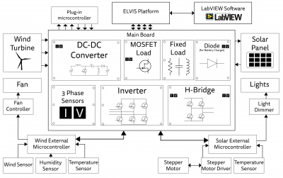
The Solar External Hardware block includes: a PV panel; a stepper motor; a lamp box; sensors; and the mechanical structure that holds these components together. The stepper motor controls the angle of the PV panel. The lamp box will simulate the sun and consists of down lights, down light transformers and a dimmer. Sensors include a temperature sensor and a light intensity sensor.
The Wind External Hardware block includes: a wind tunnel; wind turbine and generator; and sensors. The generator is a hobby BLDC motor. The sensors include wind speed, temperature and humidity sensors.
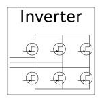
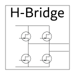
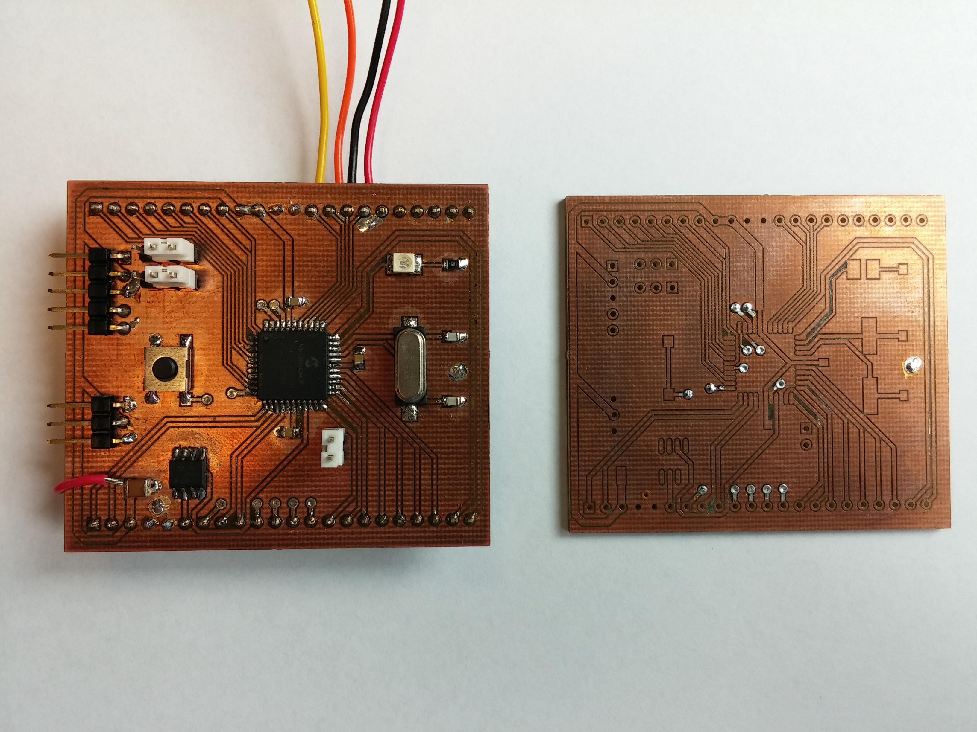
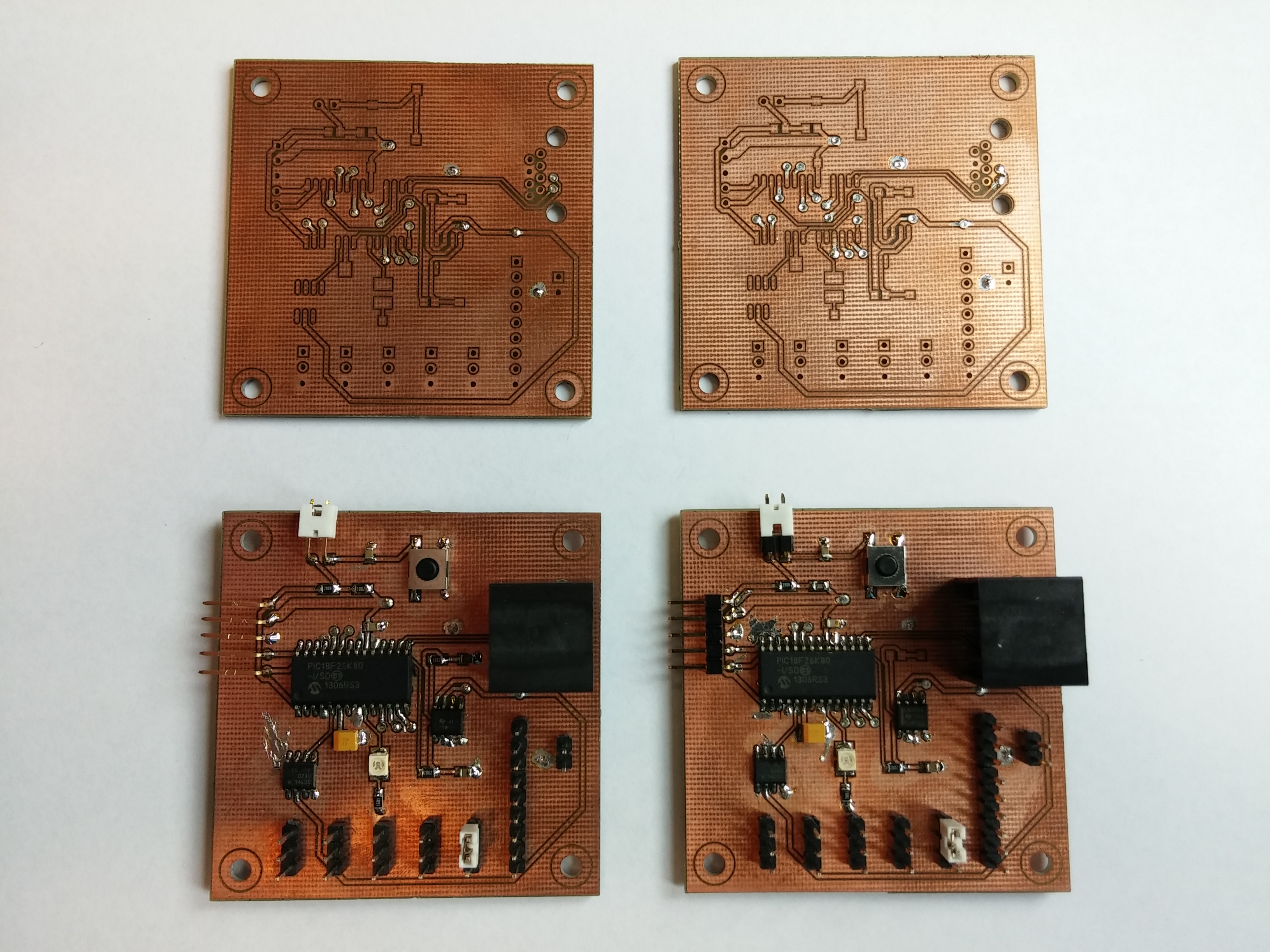
One main PCB and several sub PCBs will be designed and constructed in this project. The main PCB will provide circuitry and data acquisition capability required to find the characteristics of the PV panel and the wind turbine. Two fixed load PCBs will provide a platform of the RL and RC tests for the wind system. A microcontroller PCB will control the buck/boost converter, 3 phase inverter and 1 phase H-bridge inverter. External microcontroller PCBs will also control and receive data from the wind speed sensor, temperature sensors and the humidity sensor.
The desktop computer will run an educational LabVIEW program that will be developed in this project. The LabVIEW program will guide students through experiments, and allow students to control on-board and external hardware, take measurements from on-board and external sensors, and analyse those measurements.
Wind System
The wind system includes the electric fan, fan controller, wind external micro-controller, wind speed sensor, humidity sensors and temperature sensors.
the wind tunnel provides the uniform wind for testing. The electric fan is on top of the wind tunnel. The electric fan is controlled by LabVIEW through external wind micro-controller. The electric fan can provide the wind power to the wind turbine.
Wind Tunnel
A variable pitch propeller and motor set is used for the generator initially. The set used for the test is a 1600KV motor and a 10-inch diameter propeller. It generates power at 1600rpm/V. The wind turbine is controlled by LabVIEW and the three phase AC power signal will be sent to the main board for further test.
The wind power generated by the wind turbine can be calculated from the equation P=1/2 ρAC_p v^3, where P represents the power generated by the wind power; ρ represents the air density; C_p represents the efficiency of the wind turbine; A represents the swept area of blades and v represents the wind speed. Humidity and temperature affect the value of air density. Therefore, wind speed sensor, humidity sensor and temperature sensor are required for the wind system to calculate the efficiency of the wind turbine and take further tests. The wind speed sensor is located at the exit of the wind tunnel, right in front of the wind turbine, to get accurate wind speed near the wind turbine. The temperature and humidity sensor are located on top of the exit of the wind tunnel.
Sensors for Wind System
Experiments using the Board
| Solar |
| Wind |
- Circuits
Microcontroller Boards
Plug-In Microcontroller Board
External Microcontroller Board
LabVIEW Software
Quiz
A quiz program was developed to be integrated into the main program. It will test students’ knowledge of basic concepts before the experiment.
Experimental Panels
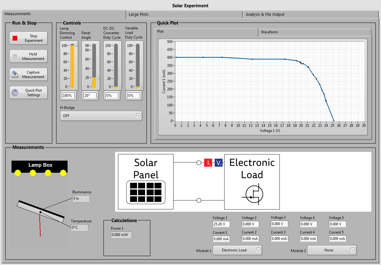
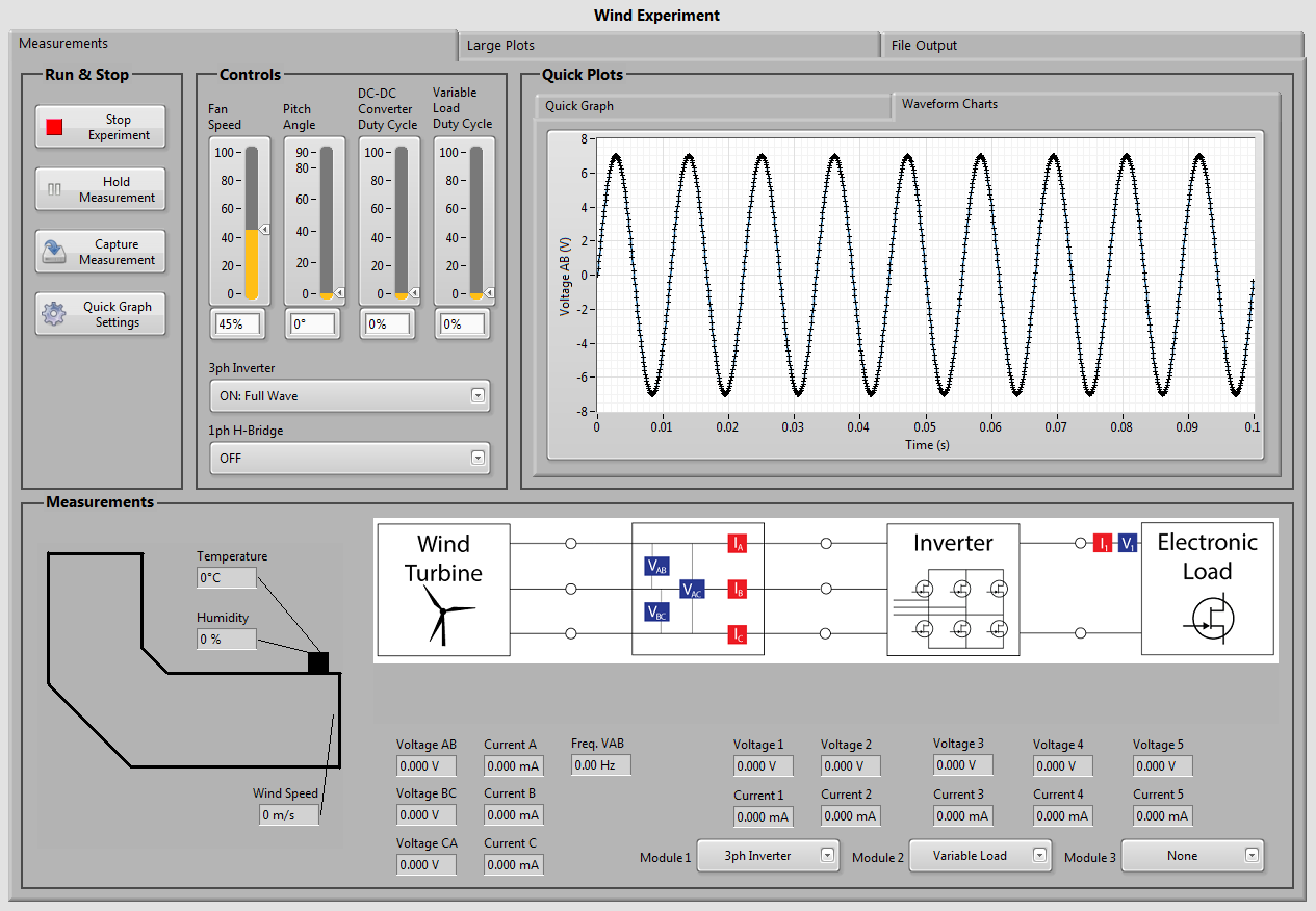
Experimental panels provide the user with controls for the various parameters of the solar system, wind system and main board. Data acquisition gets data from the sensors and this is displayed real-time on the screen. The “Capture Measurement” button allows users to capture all measurements simultaneously. Waveforms and captured data are displayed in plots for visualisation. File output features allow users to save their captured data to a spreadsheet. Students can then do post processing and generate graphs for reports.
Future Work
The output voltage of the wind turbine is lower as required. Therefore, we need to replace a lower cogging torque wind turbine for the future test and use the DC-DC converter on the main board to improve the output voltage. The wind speed, temperature and humidity sensors need to be recalibrated by using the external microcontroller so as to improve the accuracy. Further functional/operational test on the main PCB should be carried out in the future, especially on the functional/operational test of the DC-DC converter, three phase sensors, inverter and H-bridge. Additionally, the main PCB needs to be improved from the prototype version to correct mistakes such non-plated via hole pads. An informative silk screen with circuit’s representation for students also needs to be developed. The LabVIEW software will also need to be completed, tested and debugged to ensure it is reliable for students. In addition, the integration test needs to be completed so as to examine if the whole system can work together as designed.
Further than this work, it is possible that the system could easily be redeveloped in the future to work completely free of the ELVIS platform, if cost became a concern.
Team Management
Team Members
- Mr Matthew Schmidt
- Mr Benjamin Young
- Mr Yichen Huo
Supervisors
- A/Prof Nesimi Ertugrul
- Dr Hong Gunn Chew
Team Member Responsibilities
Group 1 has three members and the responsibilities have been allocated as follows:
- Matt is responsible for the solar experiment, solar external hardware, and solar part of experiment PCB.
- Yichen is responsible for the wind experiment, wind hardware, and the wind part of experiment PCB.
- Ben is responsible for LabVIEW software, plug-in microcontroller PCB and external microcontroller PCBs.
Resources
- Power Lab Benches
- ELVIS Board
- Computer
- Oscilloscope
- DC Power Supply
- Signal Generator
- Humidity Meter
- Hot Air Anemometer
