Projects:2016s1-190 Inductive Power Transfer
Contents
General info
Supervisors Info
- Supervisor: Prof. Wen L Soong
- Advisor: Dr. Andrew Allison
Team members
Asmita Dumur
Bo Zhou
Pengchao Yang
Introduction
Topic
- Transferring 5W with over 80% efficiency at given distance of 500 mm between transmitter and receiver coils
- Design of a charging surface of a standard desk, which is able to transfer 2W at least 60% efficiency
Motivation
The mainstream of power delivery, nowadays, is to advance the wireless power transmission technique. Wireless charging technology is a major theme at Mobile World Congress (MWC) in 2015. From the commercial perspective, an innovative, advanced and efficient product means more profits for manufacturers. Some well-known companies have invested in development of a better charging technique, such as Apple and Samsung. Therefore, one reason for conducting this project is that it is probably a well-paid task, and meanwhile is closely related to the current investigating trend in the technical field of power transfer. Apart from the commercial view, a main reason can be found at users’ perspective. The wireless charging system produced by this project might offer users an impressive experience. General speaking, convenience shall be primarily presented. Firstly, there are two limitations on current wireless charging products. Some light products can only charge a single device at a time. Or some cumbersome chargers can charge multi-devices at a time but they require users to place all devices on a charging pad [6]. In the project, overcoming above drawbacks should be taken into account while designing a product. Additionally, the wireless charging system is able to be a uniform charger for all different devices charging. Technically, it allows the minimum of the charging cable use [7]. Furthermore, using the system would not be limited in some particular environment. Devices can be charged even under very dirty surroundings via the wireless charging system.
Technology Background
Methods used in inductive power transfer (IPT) field
At the present there are three approaches that are able to transfer energy without using any cables. They are Microwaves, Magnetic Resonance and Laser methods [5]. These three different ways have their own features and advantages. For instance, the Microwave method is always applied in long distance electric power transmission. However, it has to apply the high frequency ranging from 1GHz to 1000 GHz, which could cause some injurious for health. Regarding to the Laser method, it can be selected to some long and small distance applications, which is flexible. Nevertheless, it also causes some health issues. The last one is the magnetic resonance method. From biological views, it is a safe way to human bodies. In the project this method is a key approach.
Magnetic resonance method
The magnetic resonance method involves the coupling of two or more coils: “ when coupled a current in one coil causes an induced voltage in the other hence under the correct conditions that voltage can be used to power some application and in these circumstances power is transferred by induction from one coil to another without physical contact.”[2]. The key requirement of this method is that the coupled coils need to operate at the resonance condition. The reasons of applying this method are able to be concluded in three points. At the beginning, the method can offer possibility of power transfers with high efficiency. For instance, for a given distance of 400mm between transmitter and receiver coils, operating at 100kHz to transfer 1kW, the complete system achieved an total efficiency >80%, which includes all the power electronics [2]. Moreover, at the view of costs for build the system, the method undoubtedly minimises the costs. It has been pointed out that the method is economical as the equipment used is cheap and easily available [5]. Ultimately, the method would be limited by environment. Covic [2] comments that such power transmission is clean and it can not be impacted by chemicals or dirt.
Equivelant circuit
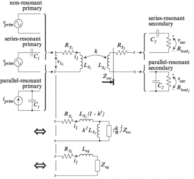
Efficiency that is being investigated and explored in the project refers to the quality of energy transmission between two coils. The discussion of the efficiency is always associated with a two-coil-circuit, which has been illustrated in the above figure . There are six combinations in total and each of them has been detailed in the following contents. Rs1 and Rs2: Parasitic primary and secondary coil resistance Ls1 and Ls2: Primary and secondary coil inductance C1 and C2: Primary and secondary tank capacitors Zeq: the equivalent impedance of the secondary reflected to the primary Req: Zeq that has become real at the phase resonance frequency (ωresp) of the secondary tank
Task 1: Coil-link system that are mainly performed at the gap of 500mm
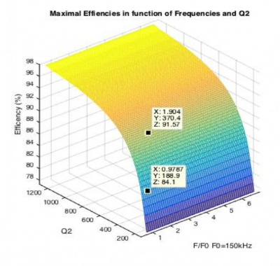
In theory, 91.57% would be a maximal efficiency that the coil link system is able to reach at which a resonant frequency would be 285.6kHz. Likewise, 84.1% as the maximum can be found at which 146.8kHz is selected. In comparison of the maximum at 146.8kHz, efficiency has been improved a lot.
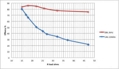
It can be found that the level of efficiency has been raised up remarkably. In particular, considering achieving the asked efficiency requirement of 80%, increasing frequency could be a proper option because efficiency would be less strict with selections of load resistances. It also should be pointed out that 85.7% was a maximum among those measured data.
Task 2: A charging surface design
Project outcome
An idea of the design
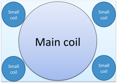
An idea for a combination of different primary coils with different sizes, as the construction of a charging surface, is presented, as shown in the following figure .
Features:
- One big coil as a main coil at the central of a surface.
- Four similar small coils as supporting coils at each corner of a surface.
- Each coil shall be switched on, depending on where a table-sized device locates.
- Coils would not interfere with each other because only one coil works at a time.
Practical outcome
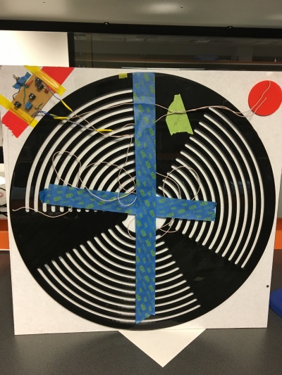
Due to time limit, there is only one small coil combined to the surface. A completed model would be like as the figure shown at previous section.
Results
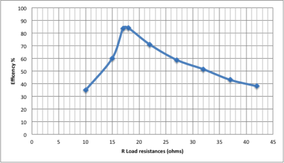
According to the Figure, efficiency rises up to 83.98% at which the load resistance is changed to 18 ohms, and then it drops as load resistances still increase. Moreover, link input power shows an opposite trend, compared to output power’s trend. What should be noted is that output power could be approximately close to 2W at which the load resistance is ranged from 15 to 18 ohms. Besides, to meet the efficiency requirement, the load resistance could be selected between 15 ohms to 25 ohms. It should be admitted that some losses were caused by other components in the practical circuit, transferring to become others like heat.
