Unused files
The following files exist but are not embedded in any page. Please note that other web sites may link to a file with a direct URL, and so may still be listed here despite being in active use.
Showing below up to 50 results in range #101 to #150.
View (previous 50 | next 50) (20 | 50 | 100 | 250 | 500)
- S21 of taperd ELC resonator and original one.PNG 1,061 × 612; 201 KB
- S11 and S21 of the complementary structure.PNG 1,074 × 608; 205 KB
- Resonant frequency with length l varied 2.PNG 992 × 571; 272 KB
- Resoant frequency with loop width b varied 2.PNG 1,001 × 585; 276 KB
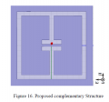
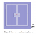
- Proposed complementary Strucuture.PNG 539 × 504; 16 KB
- Changes in resonant frequency as tapering method applied.PNG 997 × 590; 190 KB
- Comparsion between original resonator and taperd resonator.PNG 668 × 376; 23 KB
- S21 of tapered ELC resonator and original one.PNG 757 × 427; 121 KB
- Reflection coefficient S11 of the metamaterial absorber.PNG 804 × 465; 102 KB
- Proposed complementary Structure.PNG 539 × 504; 16 KB
- Comparsion between original resonator and tapered resonator.PNG 668 × 376; 23 KB
- Resonant frequency with gap size g vaired 2.PNG 1,008 × 577; 315 KB
- Resonant frequency with gap size g varied 2.PNG 761 × 448; 183 KB
- Resonant frequency with loop width b varied 2.PNG 729 × 432; 163 KB
- Comparison between original resonator and tapered resonator.PNG 686 × 373; 24 KB
- S21 of tapered complementary strucutre and original one.PNG 772 × 442; 126 KB
- S21 of tapered complementary structure and original one.PNG 772 × 442; 126 KB
- Dumb bell like structure.PNG 502 × 352; 10 KB
- Reverse feeding dual patch antennas with dumb bell structure.PNG 690 × 386; 139 KB
- S11 for single patch antenna.PNG 1,013 × 619; 92 KB
- S11 for reverse feeding dual patch antennas with dumb bell structure.PNG 1,012 × 571; 171 KB
- S11 for reverse feeding dual patch antennas.PNG 1,043 × 580; 90 KB
- S11 for dual patch antennas.PNG 989 × 599; 69 KB
- Final Year Project Timeline.jpg 2,480 × 3,505; 579 KB
- Semester 2 Timeline.jpeg 2,550 × 3,300; 344 KB
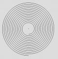
- Archimedes.jpg 629 × 634; 128 KB
- Amplifier.png 1,316 × 754; 613 KB
- 123586.jpg 751 × 478; 200 KB
- 001211.jpg 2,448 × 3,264; 1.2 MB
- Wifi shield connection.jpg 491 × 473; 47 KB
- Esd.jpg 960 × 720; 37 KB
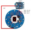
- Arduino robot.jpeg 600 × 551; 107 KB
- Webcam.jpeg 710 × 398; 17 KB
- EDF viewer.JPG 1,366 × 719; 140 KB
- Reflection coefficient for tapered MMA.PNG 620 × 405; 56 KB
- Summary for simulation and measurement in Figure 15.PNG 637 × 244; 8 KB
- 6EG$4K3)K816ML3CFL KWZ4.png 425 × 506; 33 KB
- Duration.png 1,310 × 702; 58 KB
- 002.png 587 × 504; 346 KB
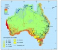
- Australian wind.jpg 587 × 504; 72 KB
- Screenshot 2015-10-19-10-28-16.png 800 × 1,280; 30 KB
- Scope.jpg 504 × 245; 29 KB
- Whole system work breakdown.png 533 × 529; 27 KB
- )$A~OSI`)QR-ZDPS0)ET`$J.png 242 × 57; 3 KB
- G-SN(ZSGX9Q0JQFEC)2)AS.png 223 × 47; 4 KB
- G69WILL2SO~40W-0GQQP%CO.png 427 × 80; 7 KB
- 2MEVQFH~V~%RH8LTL5(2%ZE.png 339 × 121; 7 KB
- 79LBXP-XFYMF7H@KJC$CZ5P.png 315 × 90; 7 KB


