Projects:2017s2-245 Novel Textile Antennas for Wearable Wireless Communications
Contents
Members and Supervisors
Project members
- Hung Quoc DANG
- Baoqi Zhu
Supervisors
- Professor Christophe Fumeaux [1]
- Dr. Shengjian Jammy Chen [2]
Abstract
Wearable antennas have used in a wide range of applications such as: wireless communications, real-time tracking and wireless medical applications. Those antennas have to be integrated into or mounted on clothing and have the stable antenna performances according to the movement of the body. Different particular applications require different antenna performances include: antenna shape, dimension, resonance frequency, gain, direction and radiation efficiency.
This project primarily examines impacts of shorting strategies on the antenna performances. The different shorting strategies are considered in this study include: full shorting wall and two shorting posts which use flexible textile materials to realize. For each shorting methods, we realized three antenna use shorting with silver fabric wall, shorting eyelets and shorting with embroidered wall.
This project also considers impact of different substrate parameter on antenna performances. There feeding techniques include: microstrip line feed, coaxial-line feed and proximity-couple feed, are also examined.
Studies also design the dual-band textile wearable antennas which are able to operate in two ISM bands: (2.4 – 2.5) GHz and (5.725 – 5.875) GHz. All of three antennas satisfy desired requirements.
Introduction
Motivation
Nowadays, Wearable Technology has been widespread used worldwide. Wearable Technology can be found in many fields of life and business. The applications of Wearable Technology are able to be categorized into three different technologies: Advanced wearable products, AI platforms and Big Data.
Wearable antenna has been become one of the most important part in wireless devices. This type of antenna has been using in many fields such as wearable transmitter and receiver, body-sensor, wireless medical applications.
Different particular applications require different antenna performances include: antenna shape, dimension, resonance frequency, gain, direction and radiation efficiency. For antenna designs, shorting is a basic component. By using shorting techniques, we can adjust the antenna performances to adapt to specific requirements.
Currently, there are several popular shorting strategies such as: folded strip, embroidered vias, eyelet and PEC. Nevertheless, the shorting strategies which realized by flexible textile material have not been popular.
This project aims to realize the impact of different shorting strategies which use flexible textile materials on the antenna performances. Base on the knowledge about PIFA antenna and shorting strategies, this project is going to design dual-band textile wearable antennas which can operate in two ISM bands: (2.4 – 2.5) GHz and (5.725 – 5.875) GHz.
Objectives
The overall aim of project is to utilize different shorting strategies which use flexible textile materials for wearable antennas. In order to achieve the overall aims, the project’s process is divided by three specific aims.
The first focus is to understand the impacts of different shorting strategies on the antenna specifications. Those shorting strategies include full shorting wall and two shorting posts.
The second specific aim is to design and realize using full shorting wall. In this project, three types of full shorting wall include: shorting wall with silver fabric, shorting eyelets and shorting with embroidered wall, were realized to achieve particular antenna specifications.
The last but not least, the final optimized antenna designs were fabricated and measured for validation. The measured results show the experimentally differences between those shorting strategies for the antenna performances.
Background
Microstrip antenna
There are a lot of antenna types such as: linear wire antenna, aperture antenna, horn antenna and microwave antenna. Among those antennas, microstrip antenna is the most appropriate for wearable application due to several features [1]:
- Simple to manufacture;
- Low cost;
- Compact, lightweight, low-profile configurations;
- Comfortable to planar or non-planar surfaces;
- Robust when mounted on rigid surfaces;
- Versatile with respect to frequency, polarization, pattern and impedance.
Wearable antenna
Wearable antennas are the special kind of antenna that can be mounted on the clothing and used for communication purposes [7]. Several important factors need to be considered while designing wearable antennas include: appropriate antenna material, fabrication methods and analysis required for a wearable antenna design [7].
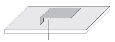
There are several conventional wearable antenna designs which include: planar dipoles, monopoles, and microstrip patches [7]. The popular planar microstrip antenna type is Planar Inverted-F Antenna (PIFA). The construction of the PIFA is shown in Fig. 3. In order to control the impedance bandwidth, we can vary the height of PIFA from the ground (less than 10mm). The feed line distance from the shorted edge of the PIFA is used to control the matching of the antenna [11]. PIFA construction is shown as:
Wearable antennas are designed to work while mounting on clothing. Therefore, there are several specific requirements for this antenna type to work effectively and safely in a body-worn context.
Firstly, wearable antennas have to satisfy SAR standards [7]. This standard has been used to consider the amount of power absorbed by the human body. The SAR limit of IEEE is 1.6W/kg for any 1g of tissue [12].
In addition, due to working in body-worn context, wearable antennas must work effectively in different bending conditions. This requirement is especially important when the antenna is mounted on arm of leg which are rounded parts of the body [7].
Furthermore, the on-body measurements have to be considered while designing wearable antenna [7]. Depend on the particular purpose of antenna, it can be applied on different part on body such as: arm, leg, chest and back. Therefore, it is important to measure the antenna performances at particular body part.
Impacts of different shorting strategies on antenna performances
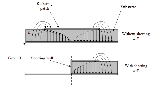
As mentioned above, the primary purpose of shorting strategies is to miniaturize the patch by creating something similar to electric wall. By using shorting strategies, the antenna dimension is reduced significantly.
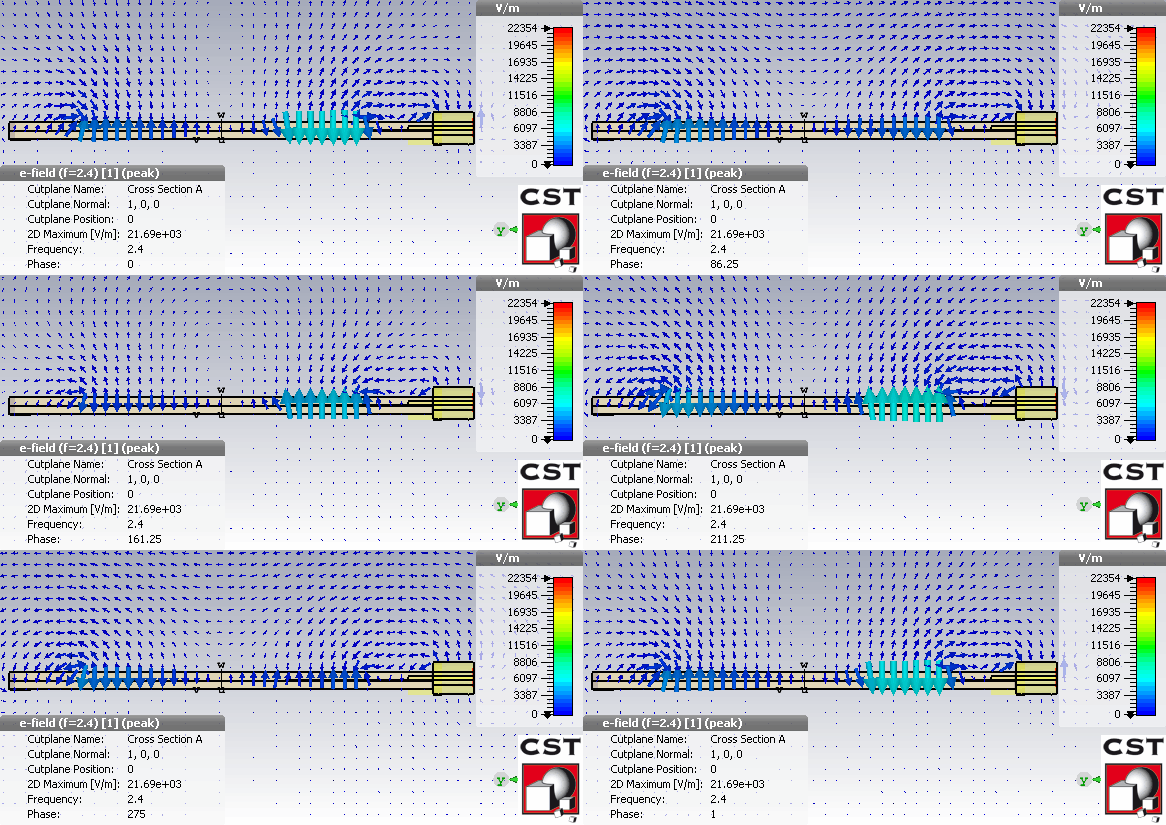
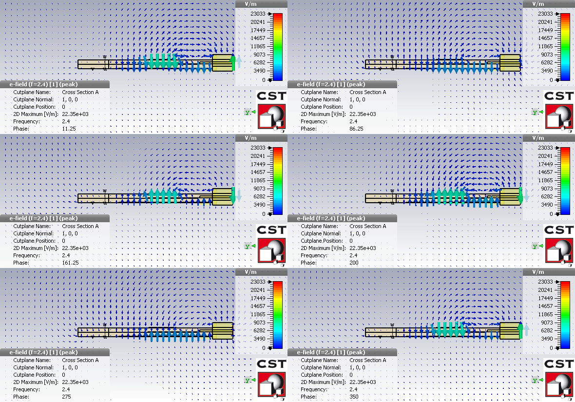
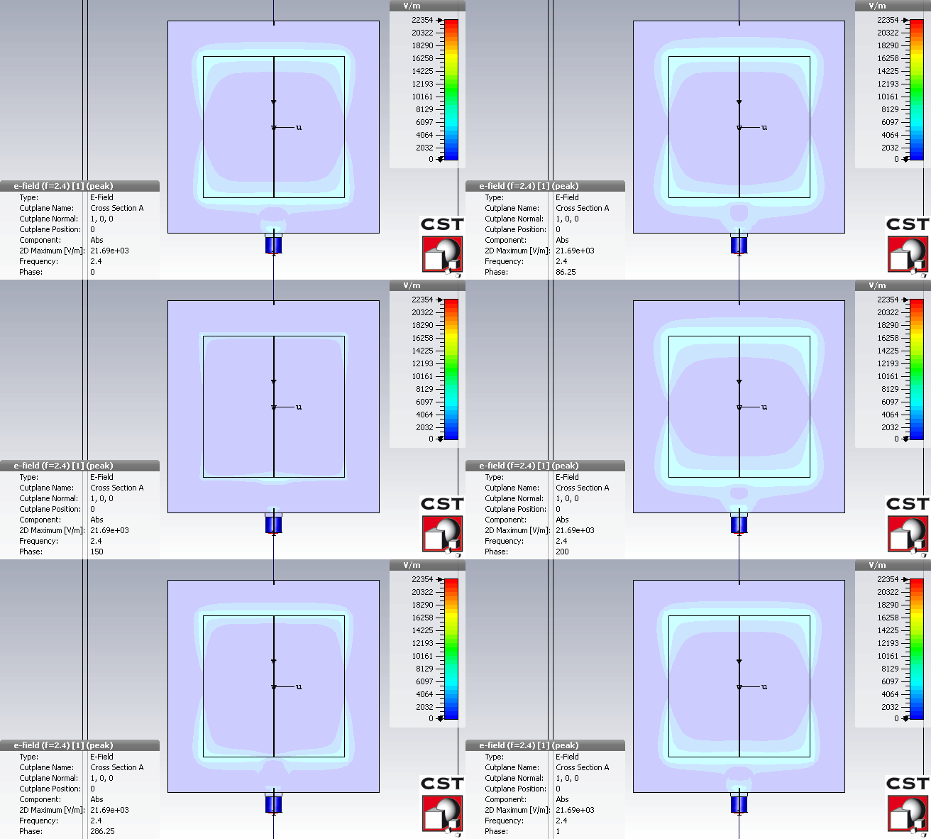
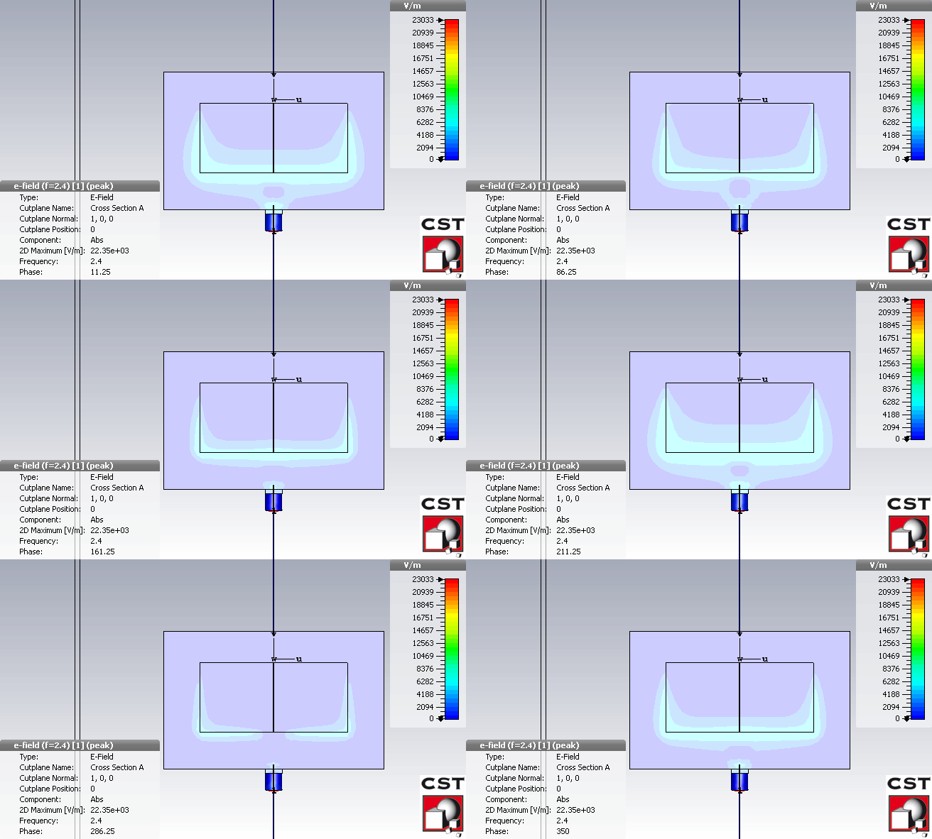
While shorting wall is placed, the patch and ground are connected. The patch current goes straight to ground instead of be forced to be zero (without shorting wall). At this time, we only need to use the lower half of the cavity to radiate the same resonance frequency with the full patch antenna, the upper half mode is shorted. The fringing fields are shorted at the shorting wall position. At this time, only the fields near the feeding path are used for radiation. Although this method led to the reduction of antenna gain, all other basic antenna performances are similar to the full patch. The difference in Electric field distribution between the full patch antenna and the antenna using shorting wall is shown as:
New Wearable textile antennas
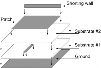
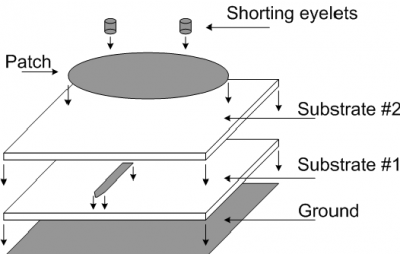
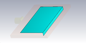
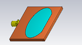
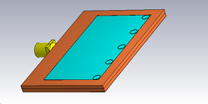
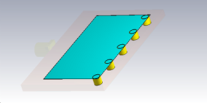
The processes used to create full shorting wall and two shorting posts antenna are shown as:
Three types of textile wearable antennas are realized in this section. Those antennas have to satisfy several specific desired requirements as:
- Operating in the 2.4 GHz and 5.8 GHz ISM bands. In particular, with respect to 50 Ω resistance, the 10dB return loss bandwidths are: (2.4 - 2.5) GHz and (5.725 - 5.875) GHz;
- Antenna radiation efficiencies are better than 80%;
- For wearable purpose, the vital requirements for antenna is small size, flexible and lightweight;
- Antenna performances have to be stable under several particular working conditions include: body movement, different bending conditions.
The conducting silver-fabric with 0.01 Ω/sq of resistance has been selected for the realization of the patch, feed line and ground plane. This material fulfills the requirements for wearable antenna without the compromising the performances of the antenna [4].
The lightweight, water resistance and flexible PF4-foam will be used for substrate. Based on the experiment in section 5.3.1, by using PF4-foam, the requirements of resonance frequency, antenna gain and efficiency are satisfied. Two layers of substrate are required for proximity-couple feed technique. Each substrate has 1.6mm of thickness, therefore, the total thickness is 3.2 mm.
In order to realize the shorting eyelets, we used copper which satisfies conductive, lightweight and easy fabrication requirements. Copper is also soft enough to easily put on the antenna.
Antenna designs
Antenna with shorting silver fabric wall
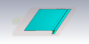
Antenna with full shorting silver fabric wall configurations are shown as:
Antenna with two shorting silver fabric strips configurations are shown as:
Antenna with shorting eyelets
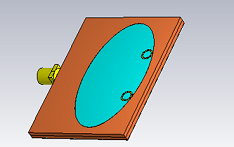
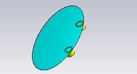
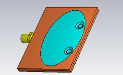
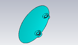
Antenna with full shorting eyelets configurations are shown as:
Antenna with two shorting eyelets configurations are shown as:
Antenna with embroidered wall
Antenna with full embroidered wall configurations are shown as:
Antenna with two embroidered posts configurations are shown as:
Antenna fabrication
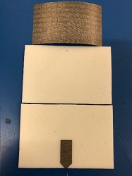
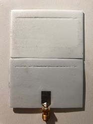
All antennas were fabricated in the following steps:
- Follow the dimension as simulation, the silver fabric was cut to 3 pieces for top patch, ground plane and feed line. The 1.6mm PF4-foam also was cut to 2 pieces for 2 substrate layers;
- The ground plane and feed line were attached to the lower substrate using fabric glue. SMA connector was connected to the feed line by conductive epoxy;
- The top patch and upper substrate will be processed later corresponding to different shorting strategies.
Shorting silver fabric wall
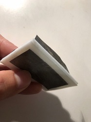
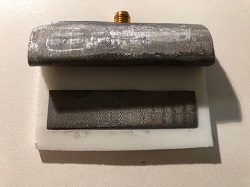
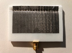
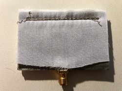
In order to make the shorting wall, the top patch was cut by 10mm longer than simulation (35 mm in particular in comparison with 25mm in simulation). The extended patch will be used to make the shorting wall. After that, the extended path of top patch was put through the substrates to make the shorting wall. This path was attached to ground by conductive epoxy. Fabrication process is shown as:
Shorting eyelets
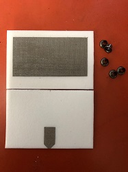
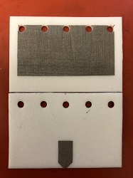
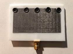
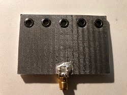
For shorting eyelets, at first, the top patch was attached on the upper substrate by fabric glue. After that, we use the eyelet punch to make holes for eyelets. We were use the eyelet tool to mount the eyelets to the antenna. The last step is to attach 2 substrates together by fabric glue. Fabrication processes for shorting eyelets are shown as:
Embroidered wall
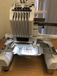
In order to fabricate embroidered wall, the top patch was also attached on the upper substrate by fabric glue. Embroidered wall model is created by PED-basic software. To create the embroidered wall, we used embroidery machine. The conductive thread was used for both top and bottom of embroidered wall. The stitch step length was selected as 3 mm and the embroidery machine was set to repeat a total of 5 times to increase the embroidered wall density. Embroidered wall fabrication process is shown as:
Simulation and measurement results
In order to measure the reflection coefficient |S11|, we use Network Analyzer machine. By using the same port to transmit signal to antenna and receive the reflection signal from antenna. The Network Analyzer will compare those signals and give us the result about reflection coefficient |S11|.
The radiation pattern at the center frequency as well as antenna gains and efficiencies corresponding to two frequency bands are validated by 3-D measurement in the anechoic chamber. Antenna was set in the Anechoic Chamber is shown as:
Shorting silver fabric wall
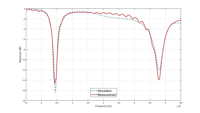
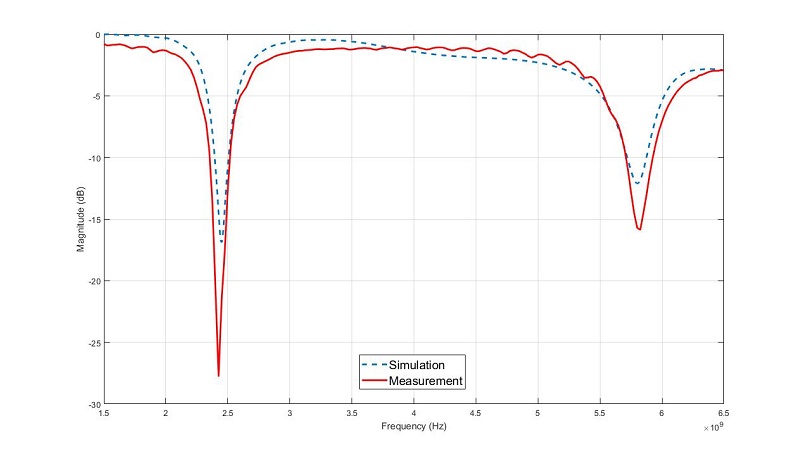
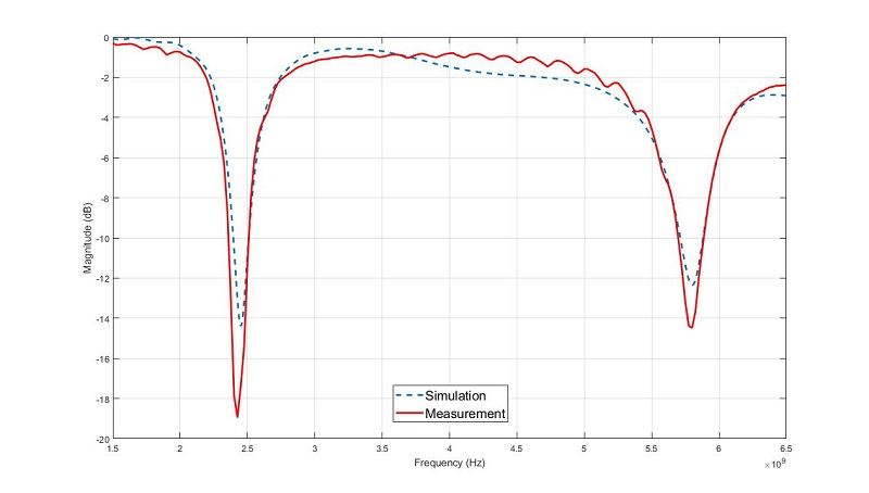
Simulated and measured reflection coefficients diagram of antenna using shorting silver fabric wall is shown as:
We can see the good agreement between the simulated and measured values is proved. The antenna with shorting wall completely covers the 2.4 GHz ISM band and 5.8 GHz ISM band with the bandwidths are (2.38 - 2.51 GHz) and (5.69 - 5.88 GHz) respectively.
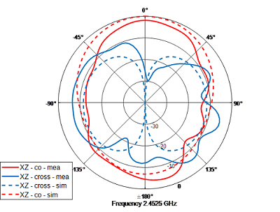
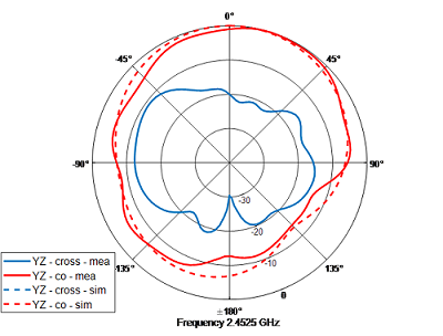
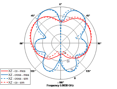
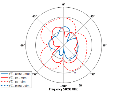
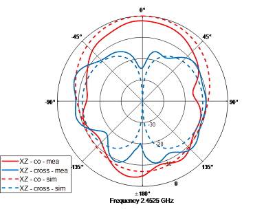
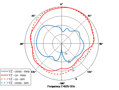
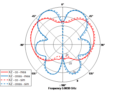
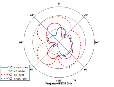
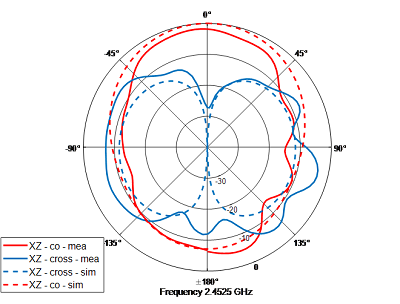
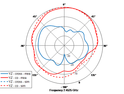
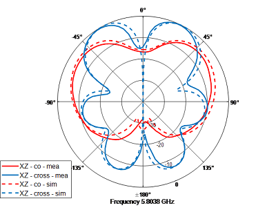
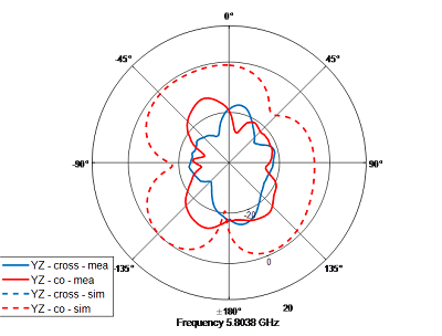
Measured and simulated realized co- and cross-polarizations for antenna using shorting silver fabric wall at both 2.45 and 5.8 GHz are shown as:
Shorting eyelets
Simulated and measured reflection coefficients diagram of antenna using shorting eyelets is shown as:
We can see the good agreement between the simulated and measured values is proved. The antenna with shorting eyelets completely covers the 2.4 GHz ISM band (2.35 – 2.53 GHz) and 5.8 GHz ISM band (5.71 – 5.92 GHz).
Measured and simulated realized co- and cross-polarizations for antenna using eyelets at both 2.45 and 5.8 GHz are shown as:
Embroidered wall
Simulated and measured reflection coefficients diagram of antenna using embroidered wall is shown as:
We can see the good agreement between the simulated and measured values is proved. The antenna with embroidered wall completely covers the 2.4 GHz ISM band (2.36 – 2.51 GHz) and 5.8 GHz ISM band (5.7 – 5.89 GHz).
Measured and simulated realized co- and cross-polarizations for antenna using embroidered wall at both 2.45 and 5.8 GHz are shown as:

![Microstrip antenna [1]](/projects/images/6/67/Microstrip_antenna.png)
