Projects:2017s2-270 Reconfiguration on Multi-Agent Systems (Robots Systems)
Team Members
Chenkai Xu
Yonghao Peng
Junbang Tian
Supervisors
Peng Shi
Cheng Chew Lim
Contents
Introduction
Formation reconfiguration is an important issue in coordinated control for multi-agent system. The multi-agent system needs to utilize different formations to accomplish diverse missions. The relative positions of agents need to be reconfigured when specific demand is given. There will be time and energy loss during the process of formation reconfiguration. Our project group works towards an autonomous multi-agent system made up of four ground robots to achieve the dynamically reconfiguration. In the process of formation reconfiguration, we use two-stage reconfiguration strategy to reduce the time consumption or the energy consumption. The objective of our project group is to make the reconfiguration process accurate and efficient. We expect to verify the feasibility of the two-stage reconfiguration strategy by simulation experiments and field tests and to improve the two-stage strategy so that it can be adapted to more complex situations.
Abstract
The objective of this project is to work towards an autonomous multi-agent system made up of ground robots to achieve to dynamically reconfigure to cope with changes in the formation specifications based on the distribution of the agents. Two-stage reconfiguration strategy is used to make agents find a specially designated formation between the accomplishment of the mission at the most recent formation and the issuance of the next reconfiguration command, which can be called as idle time, to reduce the time consumption or energy consumption. The specially designated formation is based on the fixed number of predefined formation configurations.
System Function
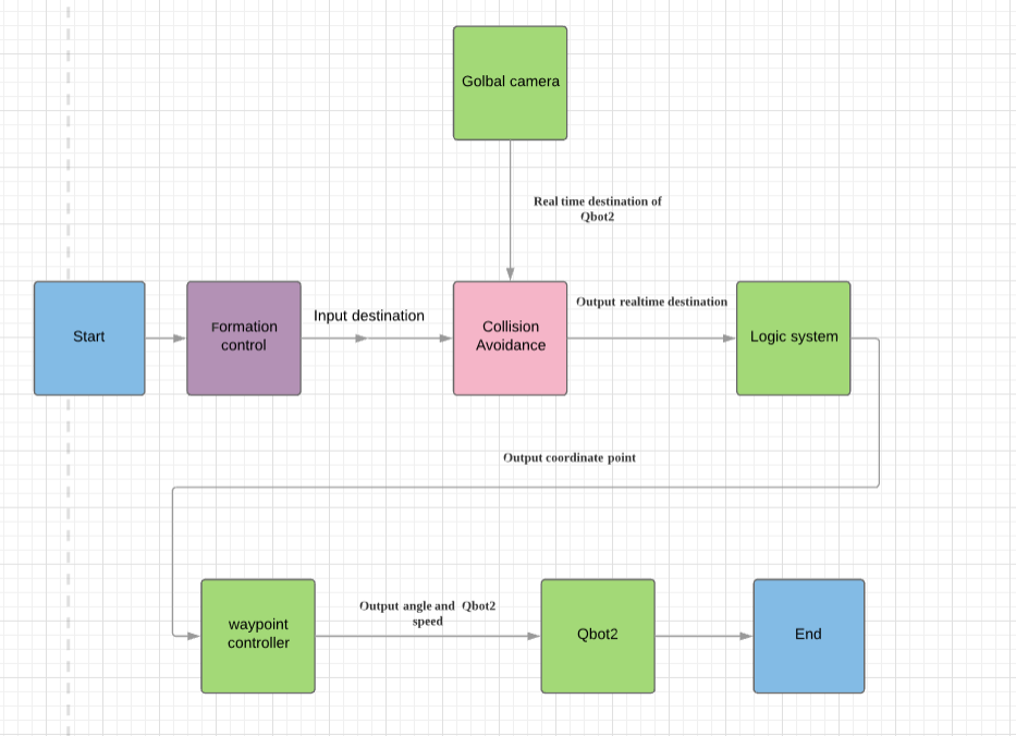
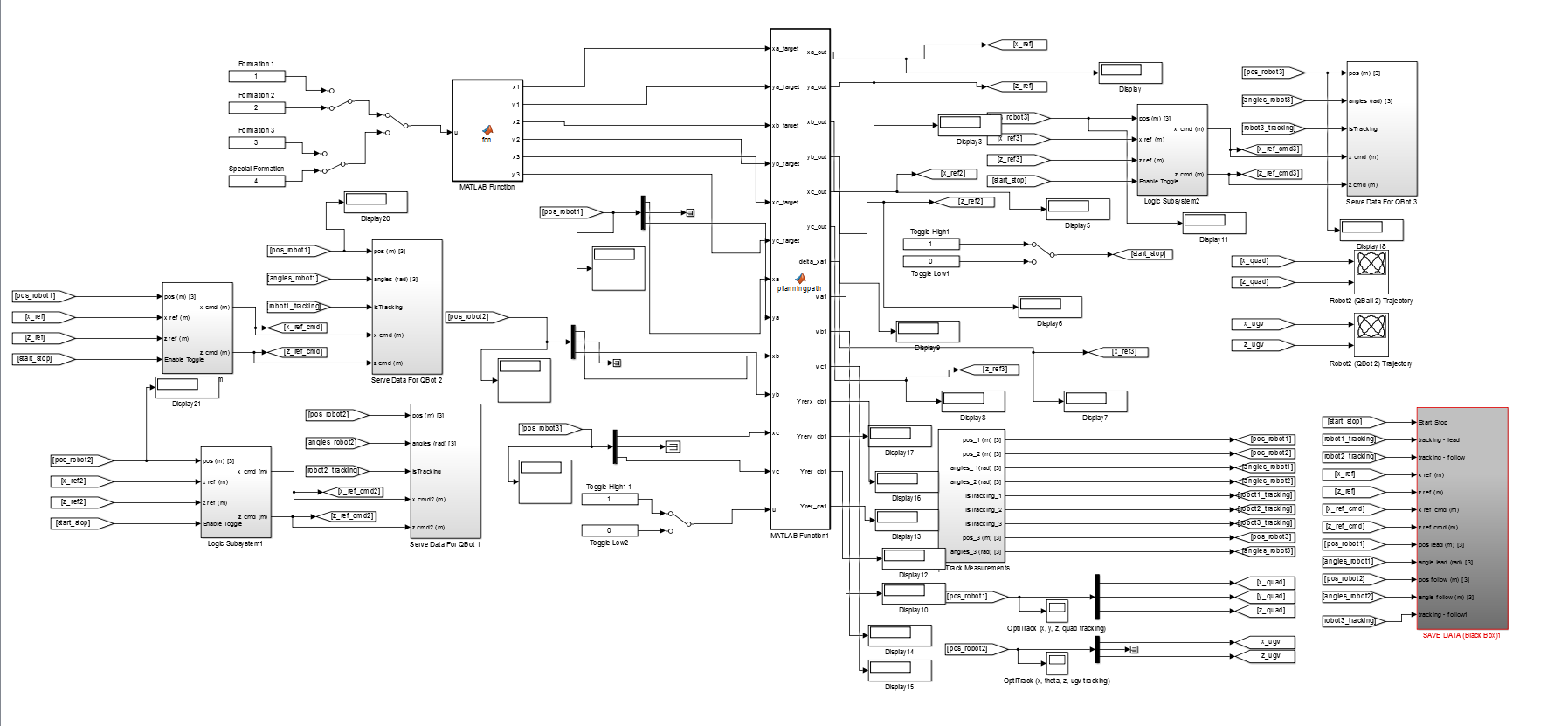
The project is divided into three main functions, formation control, collision, and motion control. Figure shows the logic figure of the Matlab system. The formation control is the first part of the system, it provides various shapes of formation, including coordinates points. In other words, it provides the final destination to the system. The collision avoidance plays an important role in this system, because it is the path planning part which means that the collision avoidance outputs real-time destination to the system. The camera provides real-time position to the collision avoidance. Then the algorithm gives the route from real-time position to final destination.
Formation control
The formation control is to design a special formation to prepare for the next command, which means that the time and energy consumption for the previous formation through the special formation to the final destination is lower than the previous formation directly to the final target position. Although sometimes, we cannot realize both the lowest time consumption and the lowest energy consumption, we can achieve one of them. During the idle time, the three individual robots need to reconfigure to pre-determined positions which need the system to use the pre-designed algorithms to calculate the second proper positions for the three robots. The special formation is the best way to get to other formations, which mean that the energy consumption directly from the initial position to all the second formations is higher than from the initial point through the special formation to the second formations.
Collision avoidance
We utilize the modified artificial potential field method for the robot's path planning. This method is to transfer the real-time problems into force problems. The goal for the specific robot has the attractive force which can attract the robot to move as close as possible to the target point. If the robot is far away to the destination, the attractive force will be larger, and the velocity will be higher. All the obstacles will generate the repulsive force to push the robots away from the barriers. For each robot, the total force is the composite force consists of the attractive force produced by the destination point and the repulsive force generated by the closed obstacles. The direction of the total force will guide the robots to move to the next coordinate, and followed by the next step to a new predetermined point until all the robots arrive in the predefined destinations.
Motion control
Controller
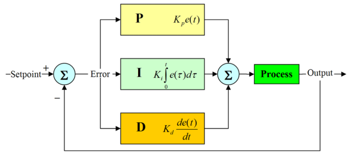
The PID control includes proportion control, integration control and differentiation control. It means that the PID control has chrematistics of proportion, integration and differentiation control and is able to eliminate residual errors, respond rapidly and advance control functions. Thus, the project decides to choose the PID control.
Camera System
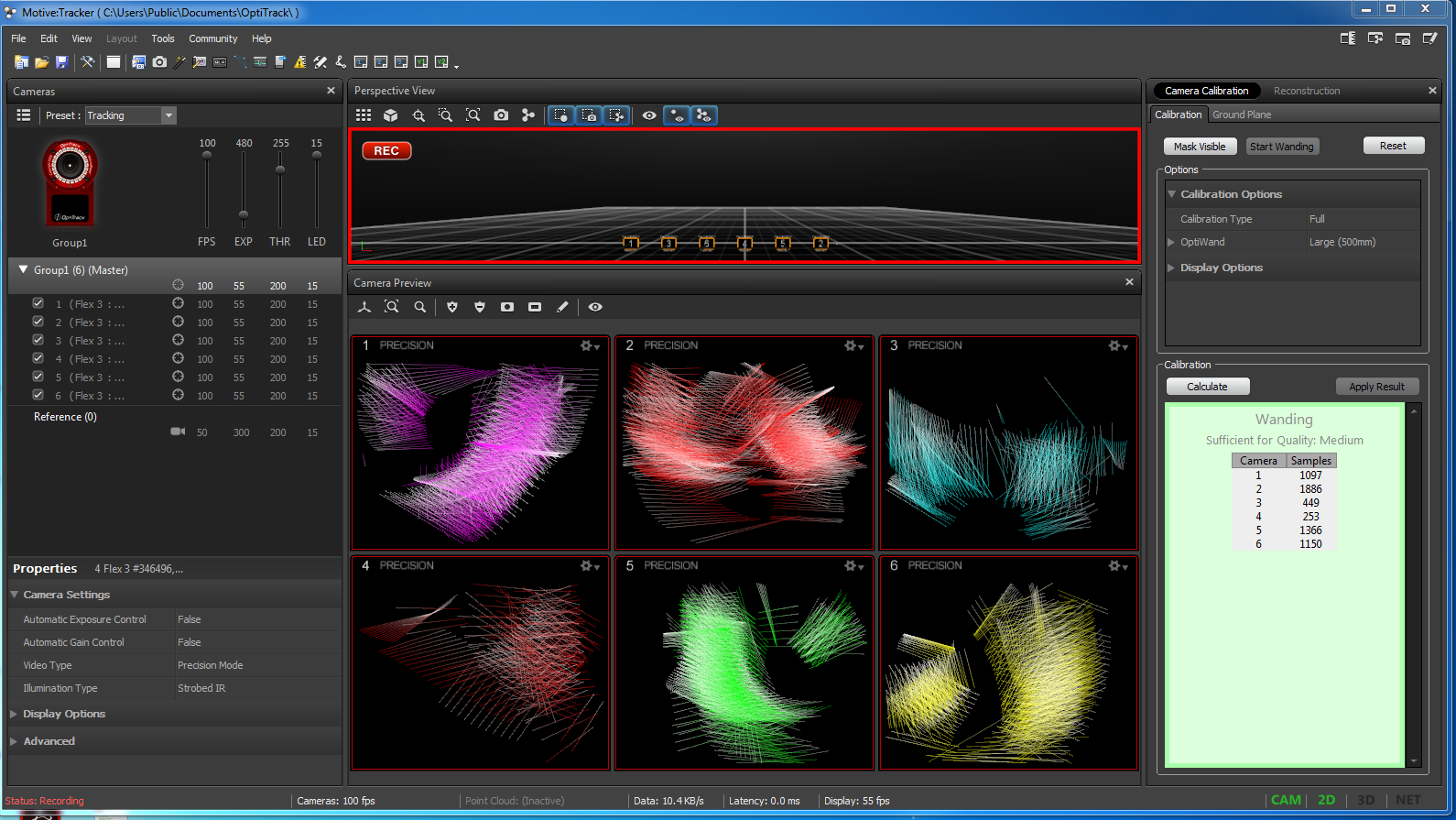
Figure shows the preparation for setting camera, using different tracks of maker to find the base aperture, then comparing the coordinate point between site and system to calculate suitable aperture. In addition, this preparation also helps motive system to adjust coordinates point error.
QBot 2 Control
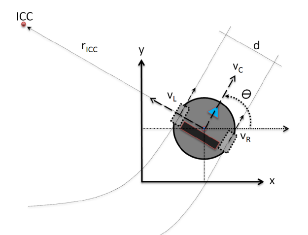
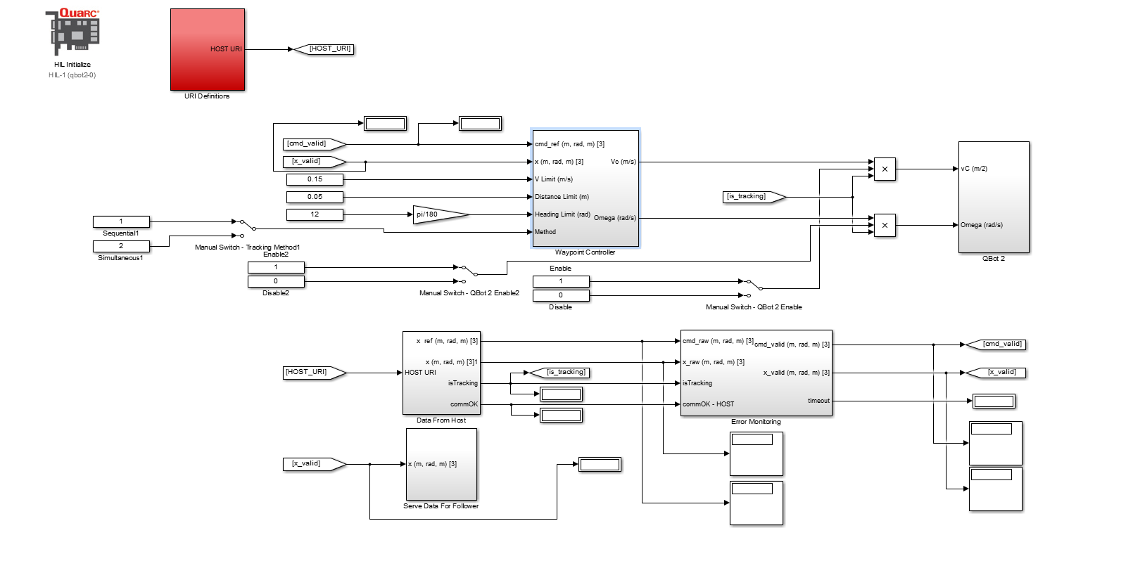
There are differences existing in the speed of two driving wheels, the robot needs to rotate around ICC (Instantaneous Centre of Curvature) which trends conjunct wheel axis of right and left. The trajectory control of QBot 2 depends on the change of the speed of two driving wheels. The wheel angular speed of QBot 2, it will be denoted as ω. The R represents the signed distance from the midpoint between the right and left wheels to the ICC. The Θ represents the heading angle of QBot 2, and Vc is the chassis centre speed. The L represents the distance between two wheels of the QBot 2. The wheel motion of QBot 2 can be summarized as: VR = ω (R + L/2), VL = ω (R – L/2). It can be found that: VC = (VR+VL)/2, ω=θ̇=dθ/dt= (VR−VL)/L, R=L/2 *(VR+VL)/ (VR−VL).
