Projects:2017s2-275 Creating Microwave Antennas with 3D Printing
Contents
Supervisor
Dr. Withawat Withayachumnankul, Prof. Christophe Fumeaux
Project Team
Chengjun Zheng, Runni Yu
Introduction
Motivation
With the development of communication technology, information exchanging has become an important issue of the research in the contemporary society. As a part of information exchanging, antennas are indispensable elements of any wireless communication system. It is prevalent for antennas as they are such useful in mobile phones, tablets and many advanced technologies. It is significant that antennas make our life easier, it could reduce the number of wires and cables. Moreover, without increasing the complexity of the system, smart antenna can expand the capacity, decrease the error rate and make coverage area larger. However, there are many research challenges remain, either to make them smaller, flexible, adjustable, or multi-functional. Meanwhile, 3D printing is an emerging technology, it provides a light, cheap way to build up things. For this project, it is interesting to combine the 3D printing technology with the microwave antenna to create a Dielectric Resonator Antenna with superior performance.
Aim
- Design and fabricate a new microwave antenna with 3D printing technology
- Designed antenna should work at 5 GHz
- The bandwidth of antenna should be between 10% and 50%
Background
Dielectric Resonator Antenna(DRA)
The dielectric resonator antenna is a kind of radio antenna, which is mainly used for microwave frequency and higher frequency. It is composed of various shapes of ceramic material. The dielectric resonator is installed on the metal surface which is the ground plane. One advantage of dielectric resonator antennas is their lack of metal parts, which become dissipative at high frequencies. Therefore, these antennas have lower loss and higher efficiency than metal antennas at high microwave and millimetre wave frequencies.The Dielectric Resonators has been widely used in the design of miniature microwave filters and oscillators. In addition to its small size characteristics, DRA also has wider bandwidth and zero conductor loss. These characteristics make them particularly suitable for working at high frequencies, so as to meet the requirements of modern communication systems. The characteristics of DRA depend on its near-field distribution, such as its working mode.
Material for Dielectric Resonator
The most popular materials used in 3D printer are Acrylonitrile Butadiene Styrene (ABS) and Polylactic Acid (PLA). Moreover, all thermoplastic materials perform well in mass fabrication. However, they are not optimized for high frequency applications, and their dielectric properties are usually poor. The dielectric properties of standard plastics are usually given at 50 Hz, which does not give any performance proof at frequencies of 1 GHz or higher. Therefore, those standard thermoplastic materials cannot be used for the fabrication of DRA. In this project, the material for the dielectric resonator uses the premix PREPERM L1000HF which has permittivity 10. For PREPERM, the dielectric measurement data can even reach 250GHz. The experimental results show that the dielectric constant of PREPURM is stable and does not depend on the frequency level. Furthermore, the chemical structure of the material has an effect on the dielectric properties. Polar materials such as polyamide and polyester show higher dielectric loss than their non-polar counterparts. In addition, additives and water sensitivity can significantly change dielectric properties in different materials. The required permittivity of Dielectric Resonator is 8, but the permittivity 10 will be used for fabrication due to the fact that the 3D printed model will contain the air bubbles which will reduce the material permittivity to about 8.
The Structure of Dielectric Resonator Antenna
The DRA could be composed of two components, the Dielectric Resonator and the PCB. The premix PREPERM L1000HF with permittivity 10 is used for Dielectric Resonator, which is fabricated by 3D printer with 100% density. Due to the fact that the air gap in 3D model will reduce the permittivity from 10 to 8. The PCB is made by copper and RT roger 5880 high frequency laminates.
Design
'Water Drop' Antenna
- The structure of double-sided PCB
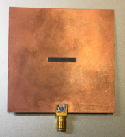
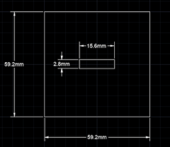
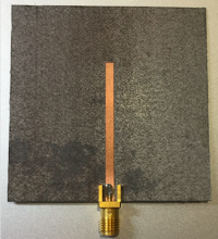
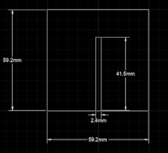
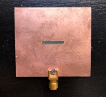
The double-sided PCB is under the dielectric resonator, which is consisted of three parts: a ground on the top of substrate, the substrate in the middle layer, and a microstrip line on the back of the substrate. The material for both ground plane and microstrip line are copper, and the thickness of them could be ignored. The substrate is using RT Roger 5880 with permittivity 2.2 as required. As I referred to the data sheet of RT Roger 5880, the thickness of 0.787mm could be used in the design.Moreover, The PCB board is a square shape and size is designed as 59.2mm*59.2mm for both ground plane and substrate. There is a slot on middle of the ground plane, the size of slot is designed as 15.6mm*2.8mm. The microstrip line is starting from the edge of substrate, the size of microstrip line is designed as 2.4mm*41.5mm.
- The structure of Dielectric Resonator
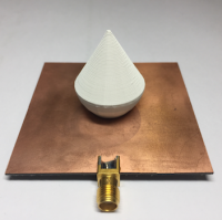
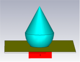
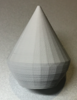
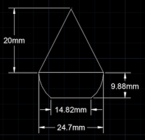
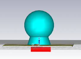
The shape dielectric resonator is designed as a ‘water drop’, it could be consisted by two parts: a part of half sphere as bottom (drop) and a cone on the top. As the drop part, the proportion among the bottom radius, height and top radius was set as 3:4:5. The proportion satisfies the Pythagorean theorem which states the square of the hypotenuse (the side opposite the right angle) is equal to the sum of the squares of the other two sides. The top diameter of the drop is 24.7 mm, the bottom diameter is 14.82 mm, the height is 9.88 mm. The bottom of cone has same diameter as the top of drop, the height of cone is 20 mm. The whole dielectric resonator is fabricated by 3D printer and the material permittivity is 10 with 100% density.
- Simulation results
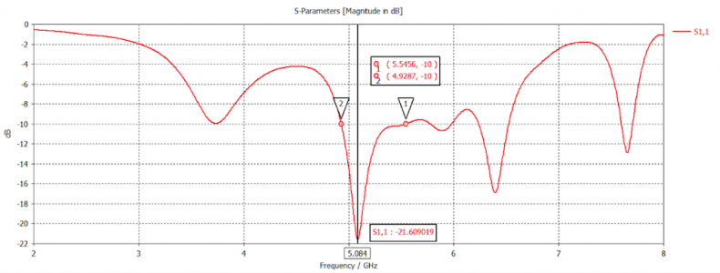
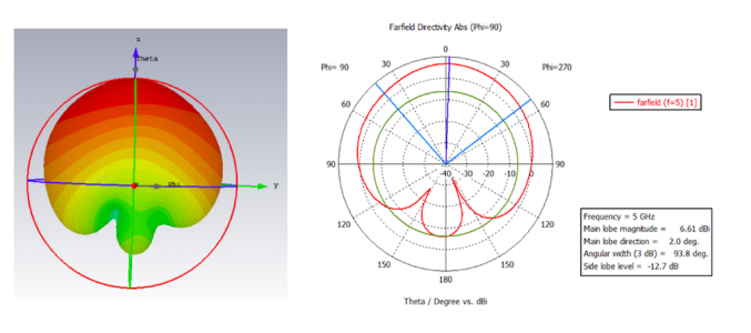
The working frequency of DRA is at 5.084 GHz. The bandwidth of DRA can be obtained by (fmax-fmin)/fcenter = (5.5456-4.9287)/5.084=12.13%. It satisfies the required bandwidth between 10% to 50%. The real part of Z-parameters is about 56.49 Ohms and the imaginary part of Zparameters is roughly 6.04 Ohms. The real part is close to 50 Ohms and imaginary part is close to 0 Ohms, which means the DRA has an acceptable impedance matching and it can work normally. The Far-field of DRA shows that the main lobe magnitude is showed as 6.61 dB and side lobe is -12.7 dB, those results are both acceptable for the DRA.
'Tellurion' Antenna
- The structure of double-sided PCB
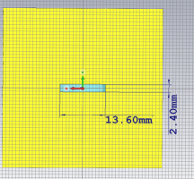
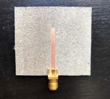
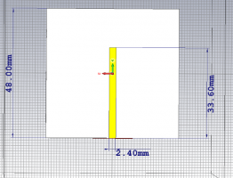
The double-sided PCB is under the dielectric resonator, which is consisted of three parts: a ground on the top of substrate, the substrate in the middle layer, and a microstrip line on the back of the substrate. The material for both ground plane and microstrip line are copper, and the thickness of them could be ignored. The substrate is using RT Roger 5880 with permittivity 2.2 as required. As I referred to the data sheet of RT Roger 5880, the thickness of 0.787mm could be used in the design.Moreover, The PCB board is a square shape and size is designed as 48mm*48mm for both ground plane and substrate. There is a slot on middle of the ground plane, the size of slot is designed as 13.6mm*2.4mm. The microstrip line is starting from the edge of substrate, the size of microstrip line is designed as 2.4mm*33.6mm.
- The structure of Dielectric Resonator
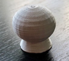
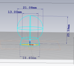
The shape of DRA looks like a 'Tellruion' which can be treated as two party: the top shape is a ball cut of bottom part and the bottom shape is circular cone cut of the top part, the radius of both cut part is 6.5mm. For the circular cone, its bottom radius, top radius and high is 8.2mm, 6.5mm and 5.4mm respectively. For the ball which is the head of DRA, the center radius of the ball is calculated with the Pythagorean theorem, as it bottom radius is 6.5mm and the center high is 8.3mm, so the radius of ball is 10.54mm. The total tall of the DRA is: high of the circular cone + ball center high + radius of ball = 25.6mm. The whole dielectric resonator is fabricated by 3D printer and the material permittivity is 10 with 100% density.
- Simulation results
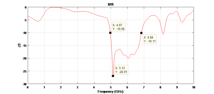
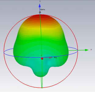
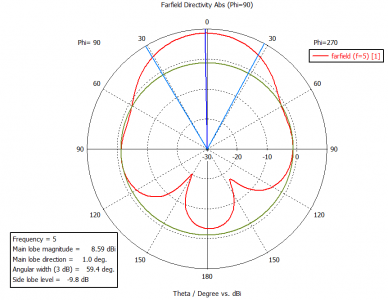
The working frequency of DRA is at 5.14 GHz. The bandwidth of DRA can be obtained by (fmax-fmin)/fcenter = (6.84-4.97)/5.13=36.6%. It satisfies the required bandwidth between 10% to 50%. The real part of Z-parameters is about 54.6 Ohms and the imaginary part of Zparameters is roughly -4 Ohms. The real part is close to 50 Ohms and imaginary part is close to 0 Ohms, which means the DRA has an acceptable impedance matching and it can work normally. The Far-field of DRA shows that the main lobe magnitude is showed as 5.89 dB and side lobe is -9.8 dB, those results are both acceptable for the DRA.
Conclusion
This project provides the basic principles to learn, the simulation results of both designed DRA have met all requirements. To be specific, the resonate frequency of both DRA are operating at about 5 GHz, the specific DRAs were printed out by 3D printing technology with the setting values. Furthermore, the PCB was fabricated and the bandwidth of both DRAs are between 10% and 50% . However, this is not considered as the end of the project, future development for the DRA should be worked out in the future research.
Future Work
- Finish the measurement for each DRAs.
- Compare the measurement results with simulations and optimize the designs
- How the shape or material will influence the antenna radiation pattern research and study in the future
- The method of how to balance the error between material using in design and the actual using in fabrication can be founded in the future.
References
[1] C. A. Balanis, “Analysis and Design,” in Antenna Theory, 2th ed. New York, 1982.
[2] W. Baines, R. Dahle, “Enhanced Bandwidth Microstrip Patch Antennas Through 3-D Printing,” 2016.
[3] S. Moscato, R. Bahr, T. Le, M. Pasian, M. Bozzi, L. Perregrini, M. M. Tentzeris, “Infill-Dependent 3-D-Printed Material Based on NinjaFlex Filament for Antenna Applications,” Electron. Lett. vol.15, 2016.
[4] A. Dastranj, A. Imani, M. Naser-Moghaddasi, “Printed Wide-Slot Antenna for Wideband Applications,” Electron. Lett. vol.56, no.10, 2008.
[5] A. A. Kishk, H. A. Auda, and B. C. Ahn, “Accurate prediction of radiation patterns of dielectric resonator antennas,” Electron. Lett., vol. 23, pp. 1374–1375, 1987.
[6] A. A. Kishk, B. Ahn, and D. Kajfez, “Broadband stacked dielectric resonator antennas,” Electron. Lett., vol. 25, pp. 1232–1233, 1989.
[7] K. W. Leung, K. M. Luk, and K. Y. A. Lai, “Input impedance of aperture coupled hemispherical dielectric resonator antenna,” Electron. Lett., vol. 27, pp. 2259– 2260, 1991.
[8] R. K. Mongia, A. Ittipiboon, and M. Cuhaci, “Measurements of radiation efficiency of dielectric resonator antennas,” IEEEMicrow. Guided Wave Lett., vol. 4, no. 3, pp. 80–82, Mar. 1994.
[9] A. Petosa, R. K. Mongia, M. Cuhaci, and J. S. Wight, “Magnetically tunable ferrite resonator antenna,” Electron. Lett., vol. 30, pp. 1021–1022, 1994.
[10] K. W. Leung, K. M. Luk, E. K. N. Yung, and S. Lai, “Characteristics of a lowprofile circular disk DR antenna with very high permittivity,” Electron. Lett., vol. 31, no. 6, pp. 417–418, 1995.
[11] K. W. Leung, K. Y. Chow, K. M. Luk, and E. K. N. Yung, “Lowprofile circular disk DR antenna of very high permittivity excited by a microstrip line,” Electron. Lett., vol. 33, no. 12, pp. 1004–1005, 1997.
[12] M. T. K. Tam and R. D. Murch, “Half volume dielectric resonator antenna designs,” IEE Electron. Lett., vol. 33, pp. 1914–1916, 1997.
[13] H. W. Lai, K. Luk, K. W. Leung, “Dense Dielectric Patch Antenna—A New Kind of Low-Profile Antenna Element for Wireless Communications,” Electron. Lett. vol.33, no.8, 2013.
[14] M. Ahmadloo and P. Mousavi, “A novel integrated dielectric-andconductive ink 3D printing technique for fabrication of microwave devices,” Proc. IEEE MTT-S IMS, Seattle, WA, USA, Jun. 2–7, 2013, pp. 1–3.
[15] P. I. Deffenbaugh, R. C. Rumpf, and K. H. Church, “Broadband microwave frequency characterization of 3-D printed materials,” IEEE Trans. Compon. Packag. Manuf. Technol., vol. 3, no. 12, pp. 2147–2155, Dec. 2013.
[16] M. Liang et al., “3D printed microwave patch antenna via fused deposition method and ultrasonic wire mesh embedding technique,” IEEE Antennas Wireless Propag. Lett., vol. 14, pp. 1346–1349, 2015.
[17] J. G. Hester et al., “Additively manufactured nanotechnology and origami-enabled flexible microwave electronics,” Proc. IEEE, vol. 103, no. 4, pp. 583–606, Apr. 2015.
[18] [Online]. Available: http://www.stratasys.com/3-D-printers/technology/ fdmtechnology [19] R. Moro et al., “Plastic-based Substrate Integrated Waveguide (SIW) components and antennas,” Proc. 42nd EuMC, Amsterdam, The Netherlands, Oct. 29–Nov. 1, 2012, pp. 1007–1010.
[20] S. S. MING, Analysis of Cylindrical Dielectric Resonator Antennas, Hong Kong: City University of Hong Kong, 1996.
[21] S. A. Long, M. W. Mcallister, and L. C. Shen, “The resonant cylindrical dielectric cavity antenna,” IEEE Trans. on Antennas and Propagation, vol. 31, pp.406-412, May 1983.
[22] R. A. Kranenburg, and S. A. Long, “Microstrip transmission line excitation of dielectric resonator antennas,” Electronics Letters, vol. 24, pp. 1156-1157, 1988.
[23] J. T. H. St. Martin, Y. M. M. Antar, A. A. Kishk, A. Ittipiboon, and M. Cuhaci, “Dielectric resonator antenna using aperture coupling,” Electronics Letters, vol. 26, pp. 2015-2016,1990.
[24] R. A. Kranenburg, and S. A. Long, “Coplanar waveguide excitation of dielectric resonator antennas,” IEEE Trans. on Antennas and Propagation, vol. 39, pp. 119- 122, 1991.
