Projects:2014S1-35 Human Activity Recognition to Support Independent Living
This project aims to build a Hybrid Power RFID sensor tag which could renovate the way of tag-to-reader communications based on the Wireless Identification and Sensing Platform (WISP) 4.1 DL version developed by Intel Research Seattle.
Contents
Project information
The holistic goal of the Human Activity Recognition to Support Independent Living project is to determine if the use of privacy preserving radio-frequency identification technology and wireless sensor technology to detect patient activities can form the basis for a technological solution to support independent living, specifically, build a hybrid-semi-passive sensor tag which could renovate the way of tag-to-reader communications based on the Wireless Identification and Sensing Platform (WISP) 4.1 DL version.
A WISP is generally a sensing and computing device that is powered and read by a standard off-the-shelf RFID reader [1].
Currently, there are three common approaches to provide power and tag-to-reader communications. The first one is the passive sensor tag, it receives all its operating power from an RFID reader. It is battery-free but with short wireless communication distance and the requirement of proximity to RFID reader is high [2]. The second one is the semi-passive sensor tag, it uses batteries to run the chip’s circuitry, but communicates by drawing power from the reader. The last one is the active sensor tag, it provides long wireless communication distance but in the expense of high cost and low lifetime since it requires one-time batteries to power for the tag and radio.
Project Aims
An enhanced version of the sensor tag is proposed.
The individual aim of this project is to formulate, design and build a Battery Management Unit (BMU) capable of charging/discharging under different circumstances. The BMU shall be smart to decide when to use the battery to power the WISP and be charged by the UHF reader.
It is supposed to combine all the advantages from the current three types of sensor tags and achieve better overall performance with low power consumption. Longer communication distance and better life time shall be realized.
Outline of proposed work
- Battery Test
- Building Hybrid RFID Sensor Tags
Project Approach
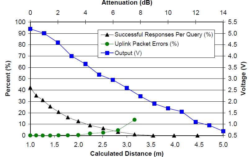
Original WISP performance
- The WISP communication and error rates as a function of RF attenuation and calculate distance.
Block Diagram
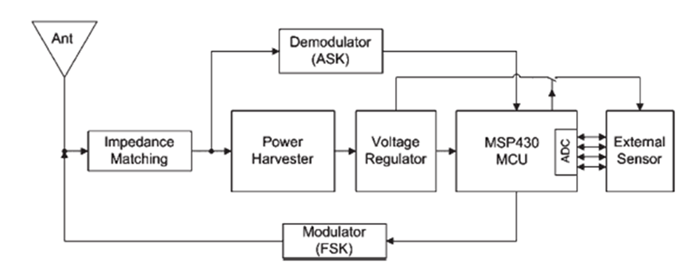
- Origianl WISP
The original WISP design block diagram with no battery.
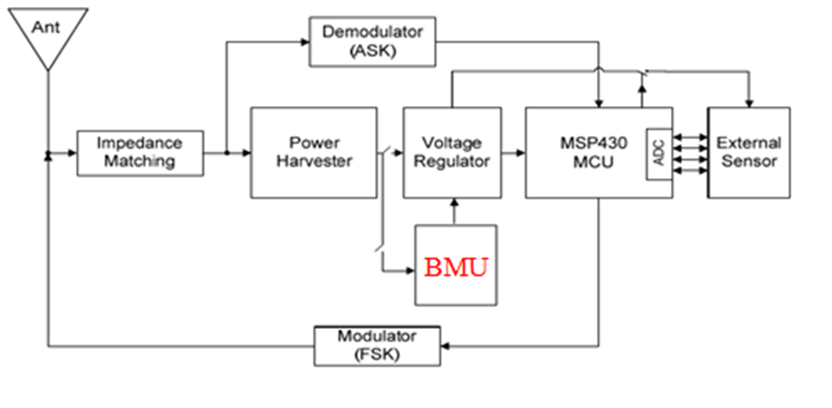
- Proposed Design
Our proposed design with Battery Management Unit (BMU). The external battery would be automatically charged and discharged under different distance between the RFID reader and the WISP corresponding to the output voltage.
Approach Description
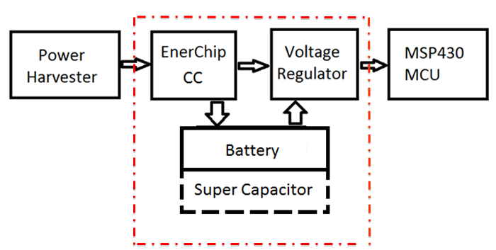
As the WISP works under ultralow current (250uA), thus there will be a great possibility that the added Battery Management Unit (BMU) would absorb most of the current and kill the rest of the system normal operation. After struggling different design by our own, the EnerChip CC series with integrated power management finally become a sophisticated power solution as the heart of our design. Here we provide two different ultimate designs block diagrams:
- Design 1
The EnerChip CC CBC 3105 with external battery or supercapacitor, a voltage detector, a traslator and a voltage regulator.
Note: By varying the R2 resistor to 360kohms when the R1 is 200kohms in order to lower the threshold voltage to 2.15V.
- Design 2
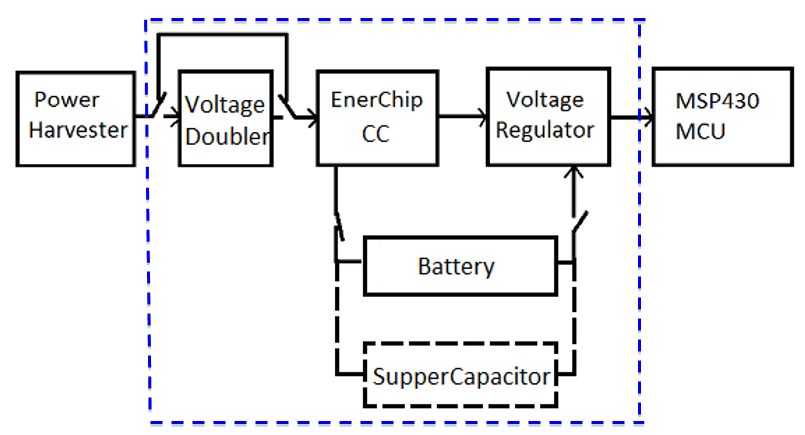
The EnerChip CC CBC 3105 with an external battery or supercapacitor, a voltage doubler, an analog switch, two voltage detectors and translators, and a voltage regulator.
Note: The BMU can automatically switch between three stages: when the voltage is between 2V and 2.5V, use the voltage doubler to boost up the incoming harvested voltage and turn off the additional 1V voltage detector; when the voltage is above 2.5V, turn off the voltage doubler and the 1V additional voltage detector; when it goes below 2V, turn on the 1V additional voltage detector.
This design tends to consume less power than the first design after the theoretical analysis and calculations.
Testing Scenario
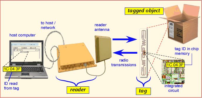
Our testing environment consists of an RFID reader and a sensor tag which is the WISP. We hold the tag and see whether if could be identified. The RFID reader sends a query to the tag and the tag returns an answer generally containing identifying information through Radio transmissions. The RFID reader sends the identifying information to our host computer, where it can be incorporated into a database to track objects and guide the activities of man and machines or revealed in human-readable form.
Technical Merits
- Longer communication distance
- Better power utilization
- Good life time
- Functionalities fully remained
- Low cost
- Ultra-small size
Design Performance
Team
Group members
- Mr Yuchen Dong
- Mr Han Xue
Supervisors
- Dr Said Al-Sarawi
- Dr Damith Ranasinghe
Resources
- USB Key Debugger
- RFID Reader, Antenna
- Standard PC
References
- [1] Intel Research Seattle, “WISP Wiki,” [Online] https://wisp.wikispaces.com (Accessed: 2 October 2014).
- [2] A. P. Sample et al., “Design of an RFID-Based Battery-Free Programmable Sensing Platform,” IEEE Trans. Instrum. Meas., vol. 57, no. 11, pp. 2608 2615, Nov. 2008.
- [3] Quick Introduction to RFID[Online], Available: http://www.polygait.calpoly.edu/tutorial.htm
