Projects:2018s1-122 NI Autonomous Robotics Competition
Contents
Supervisors
Dr Hong Gunn Chew
Dr Braden Phillips
Honours Students
Alexey Havrilenko
Bradley Thompson
Joseph Lawrie
Michael Prendergast
Project Introduction
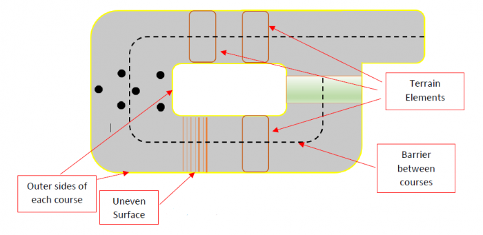
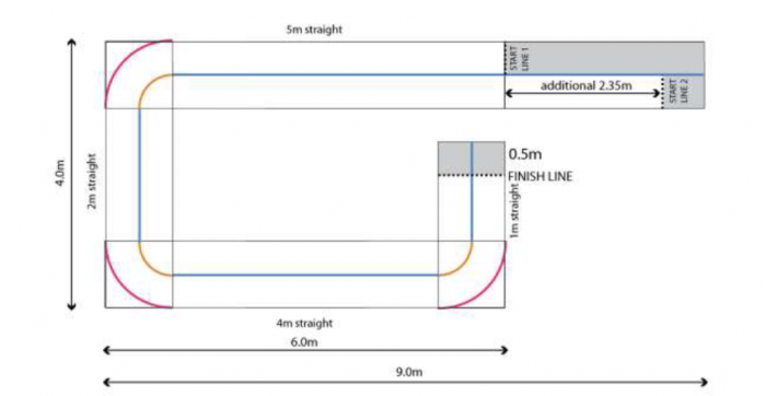
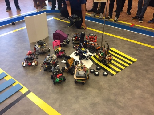
Each year, National Instruments (NI) sponsors a competition to showcase the robotics capabilities of students by building autonomous robots using one of their reconfigurable processor and FPGA products. In 2018, the competition focuses on the theme 'Fast Track to the Future' where robots must perform various tasks on a track that incorporates various hazardous terrain, and unforeseen obstacles to be avoided autonomously. This project investigated the use of the NI MyRIO-1900 platform to achieve autonomous localisation, path planning, environmental awareness, and autonomous decision making. The live final took place in September where university teams across Australia, New Zealand, and Asia competed against each other for the grand prize.
Background
Autonomous Transportation
By removing a human driver from behind the wheel of a vehicle, the likelihood of a crash due to human error is essentially eliminated. By utilising autonomous systems designed and rigorously tested by experienced automation engineers, passengers in autonomous vehicles will be able to use their commute time for work or leisure activities. By enabling communication between autonomous vehicles, traffic flow can be more efficient, and overall commute times can be reduced. Long-haul freight efficiency can also be increased as autonomous vehicles do not experience fatigue nor hunger, thereby travelling further in shorter times.
Aims and Objectives
Competition Milestones and Requirements
To qualify for the live competition, milestones set at regular intervals by NI were met. These milestones included completion of training courses, a project proposal, obstacle avoidance, navigation and localisation.
Extended Functionality
The team also decided to implement additional functionality to showcase at the project exhibition, including lane following using the RGB camera and manual control of the robot with a joystick. In both cases, the autonomous systems maintain obstacle avoidance.
Processing Platform
NI MyRIO-1900 Real-Time Embedded Evaluation Board
- Xilinx Zynq 7010 FPGA - parallel sensor data acquisition and webcam image processing
- ARM microprocessor – computation, code execution and decision making.
NI LabVIEW 2017 Programming Environment
- System-design platform and graphical development environment provided by NI
- Expansive library of MyRIO toolkits, including FPGA, sensor I/O and data processing tools
- Real-time simulation of virtual instruments to predict real-world robot behaviour
- Graphical visualisation of code execution
MyRIO processor and FPGA were programmed using LabVIEW 2017, a graphical programming environment. Additional LabVIEW modules were used to process the received sensor information, such as the 'Vision Development Module' and 'Control Design and Simulation Module'.
System Overview
Real-time robotics with computer vision is a demanding application for the myRIO processor. The system implementation combines a number of popular and efficient algorithms to smoothly navigate around the environment and detect lanes of coloured tape. To get the maximum performance, the image processing is accelerated using the FPGA.
Block Diagram
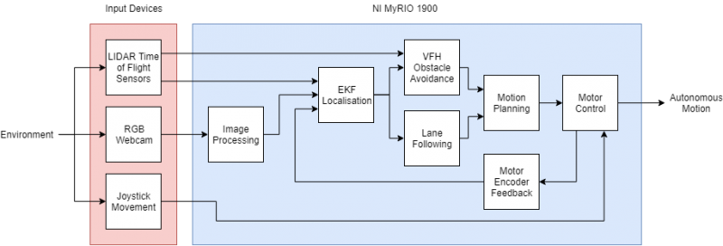
This block diagram summarises the key components of the robot's software. In the localisation block, the processed data from the main sensors is combined to estimate the robots position. A statistical tool called the Extended Kalman Filter (EKF) can merge the different information sources, estimating the position more accurately than any one sensor can alone. The Vector Field Histogram (VFH) algorithm is used to navigate around obstacles near the robot. The Dynamic Window algorithm smoothly steers the robot, and the motors themselves are controlled with a regular PID controller.
Robot Construction
Robot Frame
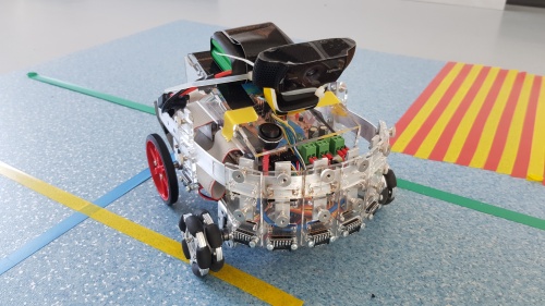
- Laser cut acrylic chassis designed in Autodesk AutoCAD
- Curved aluminium sensor mounting bar
Environment Sensors
The robot required a variety of sensors so that it could "see" track, obstacles, boundaries and the surrounding environment. Various sensors were required so the robot could calculate its position and the locations of surrounding elements.
The sensors used:
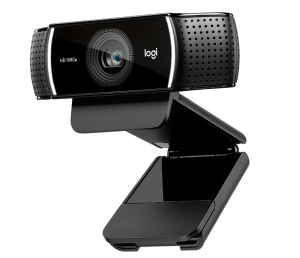
- Image sensor: Logitech C922 webcam
- Range sensors: LIDAR (VL53LOX time of flight sensors)
- Motor sensors: DC motor encoders
Image Sensor
A Logitech C922 was used for image or video acquisition. The webcam is capable to full HD image recording with a field of view of 78 degrees. The webcam was aimed at the floor in front of the robot chassis with the top of the image ending near the horizon.
LIDAR Time of Flight Sensor Array
8 LIDAR time of flight sensors were contained in a curved aluminium sensor mounting bar. Each sensor returned a value representing the time taken for a laser to reach a surface and back, to determine the range of free space on the front and sides of the robot.
Independent DC Motor Encoders
4 DC motors are used on the robot for movement and steering. Each motor is fitted with a motor encoder that returns a value representing the rotation of the motor. Using the encoders, accurate localisation of the robot was achieved.
RGB Image Processing
The team decided to use the colour images for the following purposes:
- Identify boundaries on the floor that are marked with coloured tape
- Identify wall boundaries
The competition track boundaries were marked on the floor with 75mm wide yello tape. The RGB images were processed to extract useful information. Before any image processing was attempted on the myRIO, the pipeline was determined using Matlab and its image processing toolbox.
Hough Transform
asdf
Determining Image Processing Pipeline in Matlab
An overview of the pipeline is as follows:
- Import/read captured RGB image
- Convert RGB (Red-Green-Blue) to HSV (Hue-Saturation-Value)
- The HSV representation of images allows us to easliy: isolate particular colours (Hue range), select colour intensity (Saturation range), and select brightness (Value range)
- Produce mask around desired colour
- Erode mask to reduce noise regions to nothing
- Dilate mask to return mask to original size
- Isolate edges of mask
- Calculate equations of the lines that run through the edges
The produced line equations were converted to obstacle locations referenced to the robot. Path planning could make decisions based on locations, and the robot could avoid them just as it would avoid obstacles.
Localisation
Encoder Based Localisation
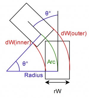
Using the encoders alone, the robot can locate itself relative to its starting point. This is done by making an assumption discussed below.
If the encoder counts for both back wheels are equal over a single time-step, the robot has traveled forwards over that time-step. If however the encoder counts are different, the robot has traveled along the circumference of a circle over the given time-step.
If the robot traveled forwards, determining the distance traveled and the direction is trivial. If however the robot has traveled along the circumference of a circle, then the robot must calculate the radius and the proportion of the circumference of the circle along which the robot traveled. Once those two are calculated, the distance traveled in x and y coordinates as well as the new orientation of the robot can be found.
This process is demonstrated in Figure X and equations 1 through to 6, where rW represent the robot width, dW represent the encoder counts (inner and outer), Arc represent the path traveled, and theta represents the change of orientation.
Extended Kalman Filtering (EKF)
asdf
Object Detection and Avoidance
Using the LIDAR time of flight sensor array, the robot is able to accurately detect obstacles at its front around to its sides. The ranges returned by the sensors are compiled in an array and matched with the relative angle of each sensor to the direction of travel.
Vector Field Histogram (VFH)
When an obstacle is detected at a predetermined range considered as too close to the robot, the obstacle avoidance algorithm takes over the steering of the robot. Two types of VFH are implemented on the robot.
Simple VFH
Simple VFH takes into account the ranges and angles of each time of flight sensor, as well as a 'panic range' which represents the smallest allowable obstacle range before VFH takes control of the robot steering. From these parameters, Simple VFH produces a histogram plot of range vs. angle, and finds the largest angular range which is free from obstacles within the panic range. The centre of this gap and the object distance are converted into a cartesian point which is passed to Dynamic Window and overrides the current target. Once this point is reached and there are no more obstacles within the panic range, navigation to the original target point is resumed.
Advanced VFH
Advanced VFH functions essentially the same as Simple VFH, however instead of finding the largest gap, it also takes into account the preferred heading of the robot that would take it closest to its target point. Additionally, a minimum gap size is specified, as well as the above parameters, to find the smallest allowable gap which is closest in heading to the desired target point. Similar to Simple VFH, this gap and obstacle distance are converted into a cartesian point for steering override, before navigation to the original target point is resumed.
Smooth Motion
Dynamic Window
While Dynamic Window is typically used as a collision avoidance strategy for mobile robots, its main function in this case was to produce smooth acceleration and braking profiles, as well as motion planning for cornering in arcs. This implementation takes into account the maximum linear and rotational velocity specified by the control system, and uses an array of different velocity profiles to determine the most optimal route to a target point, by scoring each profile against user-defined desired movement parameters including path velocity, heading to target, arc length and change in heading over the course of the arc. The most optimal path that won't overshoot the target point is then represented by the its component linear and rotational velocities and passed to the motor control loop to produce the correct wheel speeds for that path.
PID
asdf
Achievements
Partial success at NIARC 2018
- The team completed all required competition milestones and group deliverables
- A faculty grant was awarded to the team to fund travel expenses for the live competition in Sydney after demonstration of the robot capabilities
- While the robot was quite capable, the robot was knocked out of contention in the elimination rounds
