Projects:2018s1-119 Design of Calibration Platform for Medical Sensing
Contents
Supervisors
Principal Supervisor:
. Dr. Said Al-Sarawi [1]
Co-Supervisors:
. Dr. Rajiv Mahajan (RAH) [2]
. Prof. Jagan Mazumdar [3]
Project Members
. Bowen SHI
. Roziana Abdullah
Introduction
The aim of this research is to provide a platform that can be used to test the sensing sensitivity of the catheter ablation in determining its performance level. The platform that will be produced shall mimic the heart biological pulse to ensure the reliability of the test. The signal supplied will be using the voltage and frequency the same as the biological range. This determination of the device performance level can be used as a guideline in proving the accuracy of the catheter ablation being used in surgery operation nowadays.
This project is intended for use of Cardiology Department of Royal Adelaide Hospital in testing their device, known as 'catheter ablation' used in performing heart surgery. The knowledge of the near and far field sensitivity of the catheter may benefit future clinicians to have a better understanding of their device and improve the accuracy of the heart surgery.
Background
Atrial fibrillation is heart-related disease that affects the upper chambers of the heart (the atria) and causes them to quiver (fibrillate). This results in an abnormal heart rhythm (arrhythmia) affecting the pumping action of the blood around the body. Based on the literature published in 2015 [1] more than 33 million individuals worldwide have Atrial fibrillation (AF), and there are approximately 5 million new cases each year.AF incidence and prevalence increase with age, the prevalence of AF increase 3-fold for individuals in their 60s to 80s.
If this disease is untreated, it can increase risk of stroke by 5-fold, risk of dementia by 2-fold, as well as increased risk of myocardial infarction, heart failure (HF), and death. Hence the significant interest in treating and managing this disease [2].
One of the different techniques to treat AF is Surgical ablation (SA). In this approach normal sinus rhythm is restored, resulting in improving the long-term quality of life [3]. In most cases, more than 50%, the ablation is applied to the left atrium, followed by biatrial, then right atrium. The ablation techniques used can vary from on clinic to another. Example of these techniques are can vary from RF based, cryoablation, cut-and-sew lesions, or a combination of these techniques
In the RF technique, it is very significant to know the properties of the catheter's near and far fields sensitivity. The project will demonstrate the feasibility of building a hardware prototype that can be used to investigate the catheter's near and far fields sensitivity. The hardware should interface to a large size micro-pad array.
The heart operation of contraction and expansion relates closely to the flows of the electrical signal.In a healthy operation, the electrical signal enters the heart through the Sinus node (SA node) located at the right atrium and travels in a regular pattern to the Atrioventricular node (AV node). Each signal flows from the SA node to the AV node causes the atrium and ventricles to contract respective to the signal flow and beat in a regular pattern. AFib occurs when there is an additional point/s of the electrical signal entrance. This signal is usually formed at the left atrium, which is connected to the pulmonary veins that carry blood from lungs into the heart. The signal that enters the heart from the point other than SA node will misfire and causes the atrium and ventricle to beat out of sync. In relation to this rapid beating, the atria start to quiver. Click on the images below to watch the animation of the electrical flow and the heart condition in each operation [4].
Methodology
Project Equipment
1. Electrode signal source: DAC60096 EVM;
2. Device Under Test: 96 Electrode Array with different electrode size;
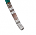
3. Catheter (Provided by Dr. Rajiv Mahajan);
4. DC Power Supply;
5. Oscilloscope;
6. Signal Generator;
7. Arduino UNO.
Microelectrode Array
Platform designed for determining the sensitivity of sensing the near field and far field of the catheter is Printed Circuit Board (PCB). The main part of the PCB is microelectrode array which will models the sensing area. Circle shaped electrodes are used where only the electrodes are left visible on the top layer and the routing is done on the bottom layer. This is to create a point-of-voltage and each of the electrodes will be individually programmed. Independently programmed electrode provide control over the activation of the individual electrodes. All the electrode will be covered with an insulation layer and the via connecting the bottom layer and the top layer will be "tented". A wall container is placed encircling the array. The container will be able to hold saline solution that represents human blood to mimic the ablation operating state.
The platform will be mounted on the DAC 60096 EVM board using the 4 headers as board-to-board connectors. DAC EVM board is a 96 channel Digital Analog Converter (DAC) which converts the digital programmed voltage to an analog output.
DAC60096 and DAC60096 EVM
DAC60096 is a 96-channel, 12-bit, low-power, serial-input, high-voltage, output digital-to-analogue convertor with conversion trigger. In other words, it is the signal source of 96 electrode array.
The evaluation model of this DAC chip was produced by Texas Instruments and it could be controlled by:
1. SPI Interface: /CS, SCLK, SDI and SDO;
2. Control logic: /LDAC, /CLEAR, STATS and TRIGG.
Findings
1)Single layer board present an increased noise in the measurement due to the coupling from the upper tracks.
2)Two layers board are preferred as they decouple the electrode array layer from the interconnect tracks.
3)Large electrode array is preferred as they provide a better coupling of the electrostatic field.
4)The signal level need to be optimized based on the thickness of the insulator, the size of the electrode array and the input signal provided at the input of the electrode.
5)An input frequency between 20 Hz and 200 Hz are needed to mimic the biological signal
Future Work
1) Expanding the Microelectrode array from 96 electrodes to 960 electrodes.
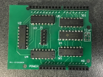
2) Software and hardware development to communicate with the 10 MDAC chips.The hardware of DAC chips controller has been designed and assembled shown in figure 3. Software has been developed as a prototype and need to be developed after the DAC x10 be produced.
3) The trade-off between the electrode array size, insulator thickness and the input signal requires further investigation.
References
[1] D. R. Van Wagoner, J. P. Piccini, C. M. Albert, M. E. Anderson, E. J. Benjamin, B. Brundel, et al., "Progress toward the prevention and treatment of atrial fibrillation: A summary of the Heart Rhythm Society Research Forum on the Treatment and Prevention of Atrial Fibrillation, Washington, DC, December 9–10, 2013," Heart rhythm : the official journal of the Heart Rhythm Society, vol. 12, pp. e5-e29, 11/18 2015.
[2] E. N. Prystowsky, B. J. Padanilam, and R. I. Fogel, "Treatment of atrial fibrillation," JAMA, vol. 314, pp. 278-288, 2015.
[3] V. Badhwar, S. Rankin, N. Ad, M. Grau-Sepulveda, R. J. Damiano, A. M. Gillinov, et al., "Surgical Ablation of Atrial Fibrillation in the United States: Trends and Propensity Matched Outcomes," Annals of Thoracic Surgery, vol. 104, pp. 493-500, 2017.
[4] Atrial Fibrillation - Understanding abnormal heart rhythm. National Heart Foundation of Australia, 2018.
[5] Texas Instruments. DAC60096 96-Channel, 12-Bit, Low-Power, Serial-Input, High-Voltage Output DAC with Conversion Trigger [Online]. Available: http://www.ti.com/lit/ds/symlink/dac60096.pdf


