Projects:2018s1-136PG Rate of Change of Mains Frequency Detection
Project Name
Rate of Change of Mains Frequency Detection (PG)
Supervisors
Keith Kikkert, Said Al-Sarawi
Team Members
Jonathon Harvey, Yixiao Zhang
Description
The Rate of Change of Frequency (ROCOF) detection of mains voltages is very important to maintain a stable electricity supply. The present IEEE standard for ROCOF detection involves converting the mains voltages to phasors and using those to determine the ROCOF. This method is called Phasor Measurement. Normally with 100 times per second updates.
C.J. Kikkert has developed a new algorithm for detecting magnitude and phase directly from the voltage waveforms, without phasor conversion or filtering. That algorithm needs some further development to accurately calculate Frequency and ROCOF with low delay and low sample to sample variations. The waveform recorders used typically have a 9.6 kSPS data rate. The new algorithm produces frequency and ROCOF values at that 9.6 kSPS data rate, so that there is less delay in detecting any disturbance.
The project involves firstly optimising the algorithm to ensure the ROCOF information provided is the best fit for the purpose of maintaining power system stability. The feasibility and performance of the new algorithm is evaluated on MATLAB/Simulink. The detecting accuracy and time delay of the algorithm are compared with the performances of the traditional PMU. The algorithm improvement will base on the results of simulation tests.
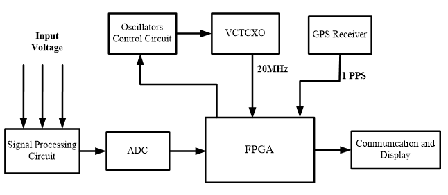
The next and biggest part is developing VHDL code for implementing this algorithm into an FPGA and implementing that in hardware. (Possibly using a commercially available FPGA development board with ADC’s added). The hardware system involves a FPGA board, voltage detection board, GPS module, interfaces and display. The detection results including voltage, frequency and ROCOF will be displayed in LabVIEW on laptop. The reference time is provided by GPS module and the VCTCXO circuit so that the detection accuracy can be guaranteed. At the end of this project, the mains frequency and ROCOF detecting should be realized in hardware.
Progress
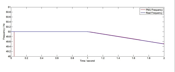
The new algorithm is tested in the MATLAB/Simulink. A Simulink combined M document simulation model is established for this algorithm. Then the feasibility and performance of this new algorithm are being examined. The following figures are the simulation results of the ramp frequency change. The main frequency is 50.0Hz at the beginning. A ramp reduce is added at t=1.0s, and the ROCOF is -0.5Hz/s. The detected result can follow the real frequency curve with almost no time delay, and the ROCOF result is equal to -0.5Hz/s, which is much faster than the three main time delay of a traditional PMU.
Yixiao Zhang realized the GPS timing, UART, communication protocol and LabVIEW monitor software. All of these functions are designed and programmed on FPGA using VHDL. The GPS timing receives GPS data from GPM-808 module. FPGA decodes the GPS data to obtain the UTC time as the system time stamp. The communication between FPGA and computer is serial communication. FPGA sends the detection results to monitor PCs. The UART port is built in FPGA using VHDL. The reporting data have 14 bytes including UCT time, voltage, frequency, ROCOF, phase, and parity check. Thus, a protocol is designed to package these bytes. This packaged data will be received by PC. A monitor software is designed to receive, decode and display the detection results. The monitor also has an alarm when frequency or ROCOF exceeds the limits.

