Projects:2018s2-279 High-Gain Antennas for Terahertz Communications
Contents
Abstract
According to Echolm’s law, data rate demands will exceed 100 Gbit/s by the year 2020 [1]. It would be impractical for the currently used Radio Microwave bands to support this data rate and so, an alternate solution will be required. A potential solution is progression to Terahertz band to utilize its higher available bandwidth available and hence, meet the data rate requirements. This project specifically investigates the requirements of antennas that will operate in the Terahertz band. Through analysis of existing high gain, high bandwidth antenna designs, this project aims to develop multiple antenna alternatives suitable for terahertz communications.
Introduction
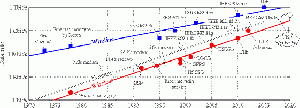
Edholm’s law, visually depicted on the red tread line in Figure 1.1, models the increase in data rates of wireless commutation standards over time. As can be observed, the model predicts that future standards will demand a data rate of 100 Gbit/s by the year 2020.
To meet this projected standard, communication technologies which utilize a greater frequency bandwidth and/or utilize this bandwidth more efficiently are required. This can be seen from Shannon’s Theorem (C=Blog_2 (1+S/N)) which shows that the data rate of a given channel, C is dependant on the bandwidth, B and signal to noise ratio, S/N of the given channel. The largest wireless band currently operating is at 60 GHz has a bandwidth of 7 GHz. To meet the 100 Gbit/s demand, this band would require a spectral efficiency of 14 bit/s/Hz, which is extremely challenging. An alternate solution, which can achieve the 100 Gbit/s demand with reasonable spectral efficiency targets, is the utilization of the terahertz band of frequencies located between 0.1 and 10 THz as shown in figure 1.2. This proposed solution is the focus area of this research project.
As observed in figure 1.2, the terahertz band in total has 9.9 Thz of bandwidth compared to 0.1 THz for the currently used Radio and Microwave bands, which results in a much higher potential data rates in the magnitude of Tbit/s [4]. As a result, the terahertz band can hold a steadier wireless data transfer rate than other high bandwidth frequency bands.
However, to take advantage of the terahertz band, there are a number of technical challenges, which must be overcome. For one, atmospheric and free space losses are increased in the Terahertz band, increasing the power loss that high gain antennas must overcome. Compounding on to this is the lossy Terahertz wave generation methods and amplified ohmic losses. Moreover, parasitic effects are amplified which increases the difficulty of impedance matching. Finally, dimensions tend to decrease with increasing frequency, which increases manufacturing difficulties. As a result, there are complications, which arise when designing terahertz band antennas that are not applicable to the currently used Radio and Microwave bands (see section 2 for more information). Resultantly, there is a shortage of antenna designs, which meet the criterion required for practical terahertz communications. Thus, further research into suitable terahertz antenna designs and how to overcome design challenges pertaining to terahertz antenna design is required.
Project team
Project students
- Nicholas Bonanni
- Stephen Li
Supervisors
- Dr Withawat Withayachumnankul
- Professor Christophe Fumeaux
Objectives
This project aims to accelerate the design and production of commercially available terahertz antennas. Also, the project aims to provide insight into how to overcome technical challenges associated with terahertz antenna design. To meet these ends, the objectives for this project will be to:
1) Evaluate range of high gain antenna designs for suitability for point-to-point communications in the terahertz band.
2) Scale, modify and simulate performance of a select choice of designs for operation in the terahertz band.
3) Manufacture chosen terahertz antenna designs and conduct practical tests to validate simulated results.
Background
Friis Equation
Friis equation is given as the following:
Where:
Pr=Recieved power at reciever antenna
Pt=Power transmitted by transmitter antenna
Gt=Gain of transmitter antenna
Gr=Gain of Reciever antenna
c=Speed of light in free space
R=Distance between reciever and transmitter antenna
f=Operating frequency
Although this equation does not take into the account attenuation losses in air, it does show the reason for the free space path loss (see the 1/f2 dependence of Pr). Additionally, it shows what factors can be altered to increase Pr and thus overcome the power loss induced by factors indicated in section 2.1. As can be observed, one could increase the power at the receiver antenna by reducing the f, but this would ultimately defeat the purpose of the project. Furthermore, there are limits to which Pt can be increased and R can be reduced in order to maintain practical power budgets and transmission distances respectively. Consequently, high gain transmitter and receiver antennas are required to overcome the power losses associated with Terahertz Band transmissions.
Antenna Gain
In antenna theory, the gain of an antenna is equal to the product of the antenna efficiency and directivity (G = e*D). The antenna efficiency, e, relates to the proportion of power inputted into an antenna which is radiated off as electromagnetic waves at the desired frequency. The directivity, D, relates to how much power is radiated in a singular direction compared to all other directions. As a result, high gain antennas radiate a large proportion of their inputted power in a singular direction [3].
S-Parameter
In the context of this project, the S parameter denotes the proportion of the power, which is reflected at the input port of an antenna in dB. It is reduced by increasing the matching between the antenna impedance and the impedance of its feed. As a result, it is beneficial for this parameter to be minimised.
Effective Area / Antenna Aperture
The effective area/ antenna aperture of an antenna is the area that receives power when acting as a receiver or transmits power when acting as a transmitter. Thus, as one can expect, the antenna aperture is directly proportional to antenna gain [3].
Phase Correction / Beam forming
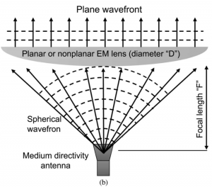
A method to increase the antenna aperture which is employed by many of the evaluated designs is phase correcting the output of a medium gain feed antenna. This process is illustrated in figure 2.1 below. As can be seen, the medium gain antenna produces a spherical radiation pattern, which propagates both normal and tangential to the intended direction of propagation direction. As a result, at a distance of “F” from the feed, the radiation pattern will be dispersed over a large aperture. However, there will be a large phase difference between the Electromagnetic (EM) waves across this aperture, which reduces directivity. To combat this issue, an EM lens or other type of phase correcting element is placed at “F” to direct the radiation in a singular direction to reduce the phase difference whilst maintaining the large aperture. Although many antenna designs employ this methodology, they all employ different types of phase correcting elements which will be compared in this report.
Method
Results
Conclusion
References
[1] T. Kürner and S. Priebe, "Towards THz Communications - Status in Research, Standardization and Regulation", Journal of Infrared, Millimeter, and Terahertz Waves, vol. 35, no. 1, pp. 53-62, 2013.
[2] "Overview", TeraNets: Ultra-broadband Communication Networks in the Terahertz Band, 2018. [Online]. Available: https://bwn.ece.gatech.edu/projects/teranets/index.html. [Accessed: 05- Oct- 2018].
[3] C. Balanis, Antenna Theory: Analysis and Design, 4th ed. New Jersey, United States: John Wiley & Sons, Inc, 2016, pp. 88-89, 791-792.
[4] M. Afzal, K. Esselle and B. Zeb, "Dielectric Phase-Correcting Structures for Electromagnetic Band Gap Resonator Antennas", IEEE Transactions on Antennas and Propagation, vol. 63, no. 8, pp. 3390-3399, 2015.


