Projects:2014S1-04 All Electric Vehicle for City Use
This project is a continuing project from 2008. The aim of the project in this year is to build an electric vehicle driving system to achieve the road test and data logging.
Contents
Project information
Motivation and Background
- The traditional internal-combustion engine causes a large amount of exhaust emission which has been proven as the major source of air pollution and Carbon Dioxide emissions. Meanwhile, the limited petroleum resources generate the requirements of new driving technology. The electric vehicle is an optimal model of electric driving technology which is treated as a feasible alternative technology. It uses battery as power source to drive the electric motor with zero-emission. Compare with the internal-combustion engine vehicle, the electric vehicle has higher efficiency on energy conversion, which would significantly reduce the energy loss. Thus, as the development of charging devices, the electric vehicle shall gain its popularization, and make crucial contributions for civil transportation and air pollution prevention in the future.
- The most significant electric motor control principle applied in this project is the Field Oriented Control (FOC). In the operation, two phase currents of motor are sampled and converted into a two co-ordinate time invariant system by Clarke Transformation and Park Transformation. By controlling the converted torque component, we can achieve the torque control as well as speed control.
Previous work
Previous years' student have developed and integrated the battery and charging system with its monitoring system, buck and boost converter, motor selection and isolation parts. For the motor driving system, Semikron SKAI5001 inverter was used to be controlled by Digital Signal Processor (TMS320F2407). This inverter was used as the main electronic device to convert DC power from battery to AC waveforms. However, the tests of Semikron inverters (either Semikron 3001 or Semikron 5001) failed in last few year. Also, the TOYOTA Prius inverter was highly recommended by last year's students consider its high power and reliable SPI communication with high-resolution current sensors. However, this inverter did not work at all after connecting to power supply. Thus, the motor control part should be built based on a new inverter and a new Digital Signal Processor.
Project Aims
The aim of this project is to converter the MAZDA MX5 with internal combustion engine to an electric vehicle use electrical energy for city use. This year, the project group is expected to achieve motor control (Field Orientated Control) based on operations of an inverter, current and position sensors that controlled by a Digital Signal Processor. The inverter, current sensors and position sensors are all required to be selected and ordered during the year to meet requirements. To achieve this target, the objective was refined into four sub-tasks:
1. Test inverter’s functionality
2. Integrate DSP with resolver to digital converter to detect rotor angle
3. Integrate DSP with current sensors to detect two phase currents
4. Program on DSP, achieve Field Oriented Control. Then do the tests on motor.
Outline of proposed work
- Order and test Resolver to Digital Converter
- Integrate DSP with Resolver to digital converter
- Achieve Serial Peripheral Interface communication in DSP
- Order and test current sensors
- Integrate DSP with current sensor
- Achieve ADC control in DSP
- Test TOYOTA Prius Inverter
- Test SemiTeach Inverter
- Integrate DSP with inverter
- Achieve inverter control in DSP
- DSP programming for FOC control
- Motor test
Project Outcome
- Resolver to Digital Converter
The Analog Devices EVAL-AD2S1210 was selected as the resolver to digital converter in this project for detecting the rotor angle.
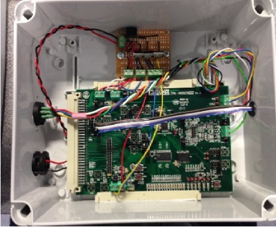
The resolver to digital converter evaluation board was set into the standalone and serial mode for integration with DSP. By using the SPI mode of DSP, the rotor angle data transmission via serial communication between was achieved.
- Field Orientated Control Program Design
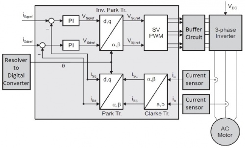
refer to the Field Orientated Control system figure, in this system, two phase currents are fed to the Clarke transformation module. Its output components i_Sα and i_Sβ are used as the input of Park transformation. Processed by Park transformation with the rotor angle, the (d, q) rotating reference frame is generated. By comparing the components i_Sd and i_Sq with input references i_Sdref and i_Sqref, the control of motor can be achieved. In this project, the motor type is PMSM whose rotor flux is fixed. Thus, the i_Sdref is set to zero. The PI controllers are used to regulate the acceleration and deceleration. After that, the output of PI controller V_Sqref and V_Sdref are fed into the inverse Park transformation. This transformation can generate the components of the stator vector voltage in the (α, β) stationary orthogonal reference frame. By calculating these two components, the space vector PWM generator will output desired PWM to drive the inverter. All these calculations are executed in DSP.
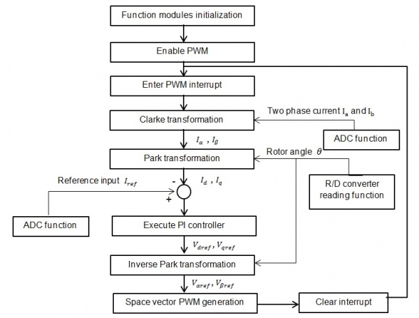
When the program starts to run, it firstly initializes the relevant DSP function modules which include PWM, ADC and SPI. Then, enable the PWM function. In each period of PWM, the function will enter into the PWM interrupt where the parameters of PWM output can be modified. So, the main calculation of FOC is applied in the interrupt which is the core algorithm. Once enter into the interrupt, the ADC function and resolver to digital converter reading function would be called to provide currents, rotor angle and input reference data. By using these parameters, the function would apply the Clarke transformation, Park transformation, PI controller and inverse Park transformation to generate space vector PWM signals. After the FOC calculation, the interrupt would be cleared and the program will enter into next loop.
- Motor Control Open Loop Test
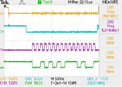
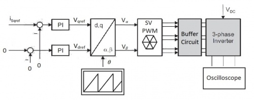
In this test, the feedback signals were set as zero. A ramp function was used to simulate the rotation of motor. The reference input i_Sqref would go through the PI controller and be processed by inverse Park transformation. The space vector would drive inverter to implement sine wave current modulation. By changing the value of i_Sqref, the amplitude of current could be controlled.
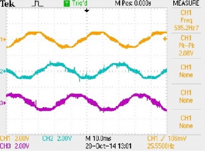
The waveforms of inverter’s output currents are close to sine wave, even there are still some harmonics. The phase difference between two phases is 120°. Also, the amplitudes of currents could be regulated successfully.
After the open loop test on static loads, the three phase outputs were connected with the motor on vehicle. A high current power supply was used to power the motor. By setting the voltage as 12V, maximum current as 20A, the motor could be driven in a low speed.
Milestones
- Proposal Seminar. (Week3, Semester1)
- Inverter switching test and verify the functionality of inverter. (Week4, Semester1)
- Connected and tested Resolver to Digital converter to the vehicle. (Week8, Semester1)
- Generate PWM signal from DSP by programming using Code Composer. (Week9, Semester1)
- Progress Report. (Week12, Semester1)
- Connected and tested current sensors. (Week13, Semester1)
- Apply 120 degrees and 180 degrees conduction tests to the inverter. (Week1, Semester2)
- Achieve ADC control and sample the output from current sensors in DSP. (Week3, Semester2)
- Achieve SPI communication between DSP and Resolver to Digital Converter. (Week5, Semester2)
- Obtain the rotor position detection. (Week7, Semester2)
- Apply FOC open loop test to generate corresponding space vector PWM signal based on initial settings of variables. (Week 8, Semester2)
- Motor Test (TBA)
- Final Seminar (Week10, Semester2)
- Final Report (Week11, Semester2)
- Exhibition (Week12, Semester2)
Team
Group members
- Mr Shuaiqi Cao
- Ms Shiyun Zhao
Supervisors
- Prof Nesimi Ertugrul
- Dr Andrew Allison
