Projects:2014S1-47 Robotic Arm for Trash Collecting Robot
This project will be working on an autonomous trash collecting robot. The focus of the group for this project will be on
the artificial intelligence and sensing aspects of the problem. A robotic platform already exists but the system will
need a robotic arm to pick up and items and place them in a bin.
Contents
Introduction
Purpose
The Trash Collecting Robot (TCR) project aims to develop an autonomous robot that can navigate around the university and collect trash while avoiding obstacles such as cars, trees humans etc. The project is divided into two separate sub-projects an Agent and a Robotic Arm each to be developed by a different group. Our group’s responsibility is to develop a robotic arm and write an interface for it to interact with an agent. The robotic arm is responsible for picking up trash and responding to requests made by agent.
Project Motivation & Previous Work
The robotic arm is one of the most useful pieces of technology to be introduced in the 20th century, and quickly became a cornerstone in many areas of manufacturing. It can be used for many different jobs and functions that may be too tedious, difficult or dangerous for a human to do. You might first think of the automobile industry when thinking about robotic arms, but they can be used for many other useful tasks besides welding and painting auto parts.
While working in a fashion similar to the human arm, robot arms can still have a much wider range of motion since their design can be purely up to the imagination of their creator. The joint that connects the segments of a robotic arm, for example, can rotate as well as moving like a hinge. The end of the robotic arm designed to actually do the work that it was designed for is known as the end effector, and can be designed for practically any task, for example gripping like a hand, painting, tightening screws and more. In our case it is design to pick up trash and place it in a bin.
There are few previous studies that have been done on trash collecting robot. Most of these studies are focusing on developing a trash-collecting robot for household where the robot navigates around the house and suck the dirt from the carpet or the floor. The TCR project however focuses on targeting general waste around the university.
Project Objectives
The project is aiming to develop a robotic arm that can be used for more than trash collection. A general interface also will be developed for the robotic arm enabling it to communicate with different platforms and performing different tasks. For this project to be considered a successful project the group has set a number of objectives to be achieved.
1. The robotic arm shall have at least 2 Degrees of Freedom (DoF).
2. The robotic arm shall be able to pick up trash weighting at least 370g.
3. The robotic arm shall have a total length of at least 50cm.
4. The gripper of the robotic arm shall be able to open at least as wide as a normal can.
5. The robotic arm shall give temperature, position, and load feedback to the agent.
6. The robotic arm shall be used for purposes other than trash collection such as playing games or demonstrations.
7. The robotic arm shall pose realistic movements (i.e. use IK to move in 3D space).
Project Plan
The project is developed base on the work of a team; the team includes two students, and two supervisors. A plan and life cycle of the project is established in the first two weeks. Additionally, every week, there is a meeting between students and supervisors; the content of the meeting is to report the progress of the project and future decision discussions. Individual tasking applied to the group members, include searching, individual planning, and documentations.
Hardware
The AX-12ACM700 Robotic Arm
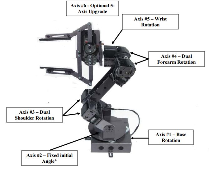
For the purpose of this project the group has decided to purchase an Off-The-Shelves robotic arm namely AX-12ACM700 shown in Figure 2. There are a number of reasons for why have the group chose the AX-12ACM700. The AX- 12ACM700 robotic arm is designed to be strong and rugged. It is constructed of anodized 0.063- gauge 5052 brushed finished aluminum components. It uses seven AX-12A actuators to provide 4 de- grees of freedom plus the gripper. Four of the AX-12As are paired up for the wrist and shoul- der joints, giving each of these joints up to 3 N- m of torque. The base, wrist rotate and grip- per joints use a single AX-12A with 1.5 N-m of torque. The gripper has a built-in adjustable sensor mount for installing cameras or other sensors [1].
The AX-12A Servo
The AX-12A actuators contain precision DC motor, gears and electronics all within a single modular package. It has 300 degrees of movement in 1024 increments with full control over speed and torque. Unlike traditional RC servos that require each servo to have its own connection to an external PWM connector, the AX-12A has its own internal controller and uses networking functionality to receive commands and send back responses. This greatly reduces the amount of cabling needed because one simply daisy chain the AX-12As together using three conductor cables (2 for power and one for data) [1].
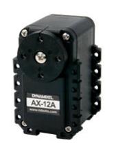
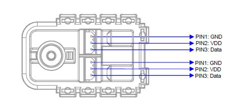

The table below summarized main specifications of AX-12 servo:

Additionally, AX-12 servo able to provide feedback including, position, Temperature, Load, input Voltage, etc.
The CM700 Controller
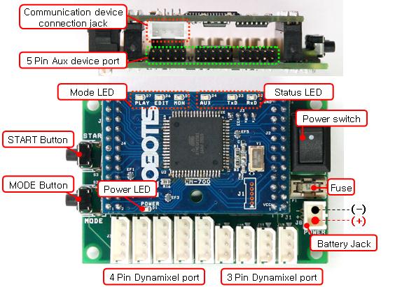
To operate the robotic arm one needs to choose a programming method and controller. There are a lot of options, including the Robotis CM-5, USB2Dynamixel, Parallax Propeller board, any computer with a serial port, any controller that can communicate at 1mbps with a serial protocol, and just about any programming language. For this project we will be using the CM700 Controller (See Figure 2). The CM700 is a new modular controller that supports a mix of Dynamixel actuators. The microcontroller, with dual bus handles both TTL (for the AX-12 servos) and RS-485 (for the RX-64 servos) communication. It is designed to work with a daisy chain of similar servos or mixture of AX-Series, RX-Series. The only limitation is that the input voltage must overlap the range of each servo used. It has an acceptable input voltage range from 7 to 27 volts [1].
The LN-101
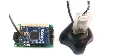
The LN-101 USB Downloader is another device included with the AX-12ACM700 robotic arm. This component is used for communication between the CM700 and the computer. To program the CM700 this component is required.More information can be found in [reference] about this component. For more information about the AX-12ACM700 robotic arm please refer to the ROBOTIS support website [4].
Software
The firmware for the robotic arm will be developed and run on the ATMega2561 micro- controller embedded into the CM700. The firmware itself was developed in the Atmel Studio environment. This allows a subset of the C++ programming language to be compiled and written to the micro-controller. The firmware for the robotic arm is comprised of modules or functional entities, which interfaces with the Robotic Arm hardware to provide necessary I/O functionality and servo control. The Robotic Arm uses CM700 which uses ATMega2561 micro-controller, which governs all the functionalities of the arm. The ATMega2561 is C programmable and thus the C programming language is used to provide all software components for this project.
Individual software modules are categorized into two major sections; namely the Communi- cation and Driver. The Communication module provides functions that employ the various peripherals available to the robotic arm. The robotic arm can communicate to other devices such as an agent or a computer using this module. The communication module provides all I/O functionalities such as handling orders and responding to requests made by an agent/- computer or by peripheral devices.
The Driver module on the other hand handles the motion of the robotic arm in 3D space. Using the kinematics of the robotic arm it provides the robotic arm with human like motions what is known as Inverse Kinematics (IK). In this section we will be describing each of this modules and their functionalities.
The Motion Module
[[File:FABRIK.png|400px|thumb|right|FABRIK First Iteration]
Given a target point in 3D space, the robotic arm is required to move to that target point as smoothly, rapidly and as accurately as possible. The best way to do this is to use IK to move the arm around in 3D space. IK is defined as the problem of determining a set of appropriate joint configurations for which the end effector of the arm move to desired positions as smoothly, rapidly, and as accurately as possible. However, many of the currently available methods suffer from high computational cost and production of unrealistic poses. A method with high computational cost is definitely undesired for our project since we are using a micro-controller with a very limited space that cannot handle complex computations.
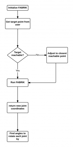
For this project we used a method called Forward And Backward Reaching Inverse Kinematics (FABRIK). FABRIK uses the previously calculated positions of the joints to find the updates in a forward and backward iterative mode. FABRIK involves minimising the system error by adjusting each joint angle one at a time. The proposed method starts from the last joint of the chain and works forwards, adjusting each joint along the way. Thereafter, it works backward in the same way, in order to complete a full iteration. This method, instead of using angle rotations, treats finding the joint locations as a problem of finding a point on a line; hence, time and computation can be saved. The following figure shows one iteration of FABRIK method.
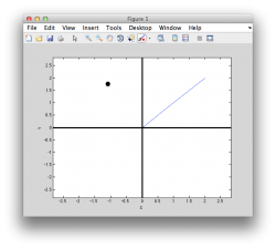
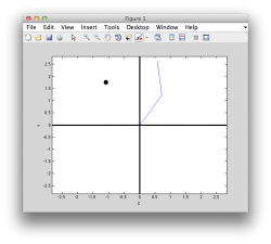
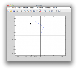
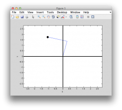
This method was simulated using Matlab and later was developed using C/C++. A sample of the Matlab simulation is shown in the follow diagrams.
The following diagram shows the overall structure of the Motion module of the firmware. This module is developed in C/C++ programming language.
Communication Module
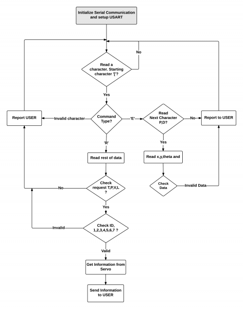
The communication module is responsible for the communication between the robotic arm and the agent. For this project we are developing an autonomous robotic arm that acts autonomously when it receives commands from an agent. The agent scans the surroundings for trash using a camera or other sensors; once trash is located the agent approaches the trash, when the trash is within the range of reach the agent commands the robotic arm to pick up the trash. The robotic arm, knowing its current position, given a targets x-y coordinates the arm starts approaching the trash and picks it up. This is the sort of communication we are required to handle for the robotic arm and the agent communication. Also the robotic arm is required to respond to requests made by the agent. For instance the agent may request the current position of the robotic arm, or the load on the robotic arm when it’s in the process of picking up an object. The Communication flow chart is shown bellow.
The Interface
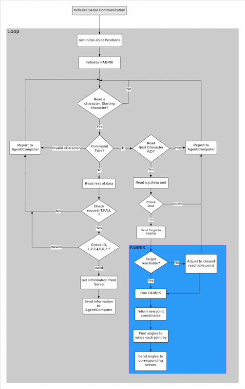
Having done both Communication and the Motion modules, we can now put this two modules together to construct the overall Interface. The overall structure of the interface is shown in Figure 20. When the robotic arm is turned on, the USART serial communication is initiated. The FABRIK method then requests the current joint positions of the robotic arm to construct the P matrix and initiate its variables. The robotic arm then waits for a command from the agent. once the command is received the robotic arm checks the type of the command. if it is a request command, then data is sent back to the agent. If it is an execution command, then the command’s values are processed. The target point is constructed from the x and y values. The target point is then sent to the FABRIK method. The FABRIK finds the angles for each join to rotate by such that the end effector of the robotic arm is at the target point and send those angles to the corresponding joint servos. The arm, upon receiving the angles will move to the desired position.
Project Outcome
A generic Interface was developed for the AX-12ACM700 robotic arm. The robotic arm is able to receive command from any agent that is capable of serial communication. It also provide the agent with information such as current position, temperature feedback and load on the arm. The arm can move in 3D space using inverse kinematics and can be used for demonstrations such as playing games and shape sorting. The robotic arm can pick up objects up to 400g, however this wait varies as the speed of the servos is decreased. This is because the output power depends on both angular speed and the torque of the servos.
Future Work
Although the project was complete and the aims of the project are achieved, there are things that could have been done better for this project. The hardware design could have changed to a better design where the robotic arm could move much more smoothly. The base for instance was modified, but could have been modified further to decrease the friction between the disk of the base and the ball bearings. Furthermore the gripper is not design to handle heavy weights, the design of the gripper could also have been changed to a much stronger gripper.
The robotic arm uses FABRIK IK to move around. Instead of using angle constraints on the FABRIK the group decided to use the angle restrictions on the servos. It is later concluded that it would deb much better to add angle constraints on the FABRIK IK method rather than use the servo angle limits reporting functionality to handle out of range objects.
Milestones
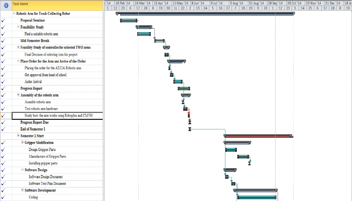
Milestone 1: Proposal Seminar (20th March 2014) Select Proposal Seminar as first milestone is because this is the first turning point for our project, which particularly means we switching Plan A build a robotic arm by ourselves to Plan B purchase one existing robotic arm.
Milestone 2: Final Decision of selecting arm for project (5th May 2014). The executed plan states that we extend our researching duration for find an arm to two weeks. At the beginning of the may we came out with a result of the selected arm, which is Cruscrawler AX12 Smart Robotic Arm.
Milestone 3: Placing the order for the AX12 Robotic Arm (7th May 2014) For ordering our selection of the robotic arm means our project tends to next stage.
Milestone 4: Assemble robotic arm (27th May 2014) To finish assemble of the robotic arm, imply that project progress result match our executed plan, which means for the next semester or the time between two semesters we can start to program the arm, and interact with aims of the project.
Milestone 5: Software design (11th August 2014) Finish software design for movement of robotic arm, finish software design for game board.
Milestone 6: Hardware modification (1th September 2014) Design gripper and base for modification and order the parts from school workshop and installing all parts together. The game board of tic tac toe game is 3D printed by school work shop.
Milestone 7: Software development (10th October 2014) Software development finished to allow arm move correctly, also Arduino and CM700 able to communicate with each other correctly. Game board is able to send feedback to the controllers.
Contributors
Team Members
- Mr Junyu GUO
- Mr Salih Al Rashid
Supervisors
- Dr Braden Phillips
- Prof Michael Liebelt
Other Contributors
- Dr. Hong Gunn Chew
- Mr. Danny Di Giacomo
- Mr. Pavel Simcik
- Mr. Ian Linke
- Mr. Brandon Pullen
Resources
Bench #7 Project Lab
[1] "CrustCrawler Robotics, CrustCrawler, Inc. 817 S. Capistrano Drive Gilbert, Arizona 85233 USA, viewed 6 March 2014"
http: // www. crustcrawler. com/ products
[2] Bill Baxter, February 21, 2000, ’Fast Numerical Methods for Inverse Kinematics’, Dept of Computer Science, University of North Carolina, Chapel Hill, NC, United States, viewed 18 May 2014
http: // billbaxter. com/ courses/ 290/ html/ index. htm
[3] S.-N. Cubero, ’A general purpose inverse kinematics method for all manipulators’ De- partment of Mechanical Engineering, Curting University of Technology, Perth, WA, Australia, viewed 18 May 2014
http: // www. usq. edu. au/ course/ material/ eng4406/ iksam. pdf
[4] ROBOTIS, 16 Technology Dr. Suite 106 Irvine, CA, USA 92618, viewed 21 May 2014
http: // support. robotis. com/ en
[5] Andreas Aristidou and Joan Lasenby, ’Inverse Kinematics: a review of existing techniques and introduction of a new fast iterative solver’, University of Cambridge, viewed 28 May 2014
http: // www. andreasaristidou. com/ publications/ CUEDF-INFENG, %20TR-632. pdf
[6] Andreas Aristidou and Joan Lasenby, ’Inverse Kinematics: Forward And Backward Reaching Inverse Kinematics’, University of Cambridge, viewed 5th JUN 2014 http: // www. andreasaristidou. com/ FABRIK. html
[7] ROBOTIS, 16 Technology Dr. Suite 106 Irvine, CA, USA 92618, viewed 20th JUN 2014 http: // www. crustcrawler. com/ smart. pdf
