Projects:2014S1-12 Exploring RF Energy Harvesting for Wearable Sensors
Contents
Project information
Introduction
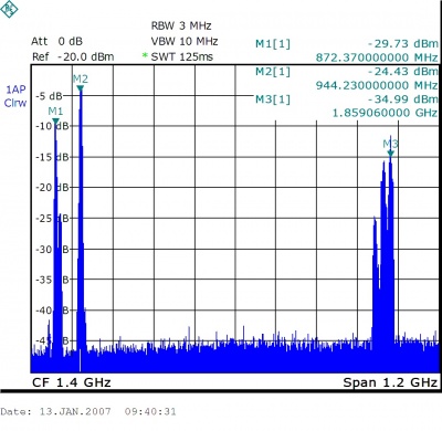
Wearable electronic devices are widely used in number of areas. The project aims to provide battery-like DC energy to low power wireless sensors by harvesting the ambient RF energy using flexible antenna and convert it through a rectifier circuit. Essentially, the antenna receives ambient radio frequency signals from mobile communication channels GSM900 and GSM 1800. The harvested energy will be then transmitted to corresponding rectifier circuits and the converted output DC energy. The output DC energy is designed to be sufficient large to drive low power sensors.
Background
A radio-frequency (RF) energy harvesting device, often referred as a rectenna, is used to convert RF energy into direct current electricity. Early rectenna researches have been done in the area of high-power beaming transmission, while more recent trends have extended to ambient microwave energy recycling [1]. With growing interest of continuous physiological signal monitoring via low power sensors as well as explosive growth of cellular mobile communications making use of large amount of base stations, rectenna applications recycling microwave energy within mobile frequency band have been made available.
Motivation
This project is particularly interesting due to the availability and the Eco-friendly design. GSM signals are prevalent in modern society with reliable propagation capability in most areas for 24/7. The final product of the project which recycles ambient RF energy can be well suit into wide range of future applications such as embedded medical systems, embedded sports equipment or consumer electronics [2] etc. Moreover, button cell batteries have less life time, smaller improvement space, plus more potential pollution to our environment.
Objectives
The aim of this project is to explore portable energy solutions which use ambient RF energy as an alternative battery-like source (DC output) to drive ultra-low power sensors.
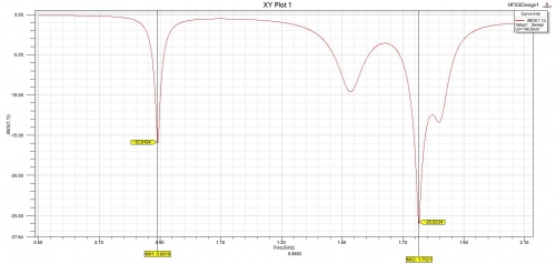
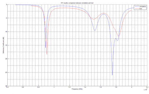
- Develop a flexible Dual-band patch antenna to harvest RF energy from GSM900 and GSM1800
- Develop a flexible Wideband dipole antenna to harvest RF energy from 780MHz to 2GHz (including GSM900 and GSM 1800)
- Develop a rectifier circuit to convert harvested RF energy to DC electricity
Design Approach
- Understand the basic approach to design antennas and the circuit of rectifiers.
- To design antennas
- HFSS is used during the design process
- Draw a parametric model in HFSS
- Obtain simulated results
- Analyse simulated results and hence optimise the design.
- Use the software to check sensitivities of the antenna performance when slightly change its dimensions. This step is used for controlling the manufacturing accuracy in the future.
- Bend the antenna in software and get simulation results since the antenna is designed to be flexible.
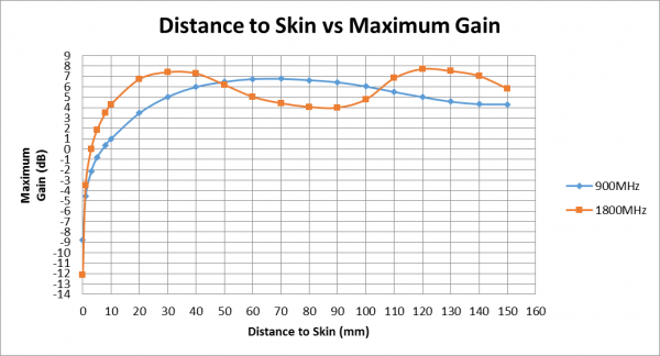
- Simulate human body effects to the performance of the antenna due to its wearability.
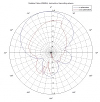
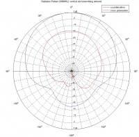
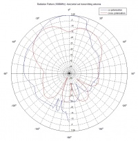
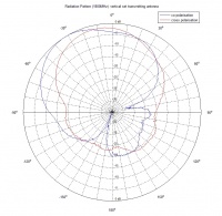
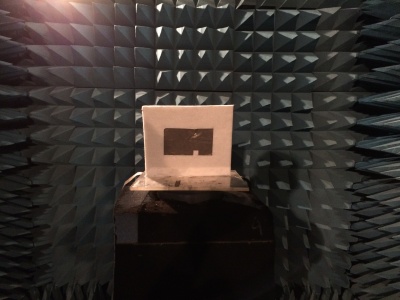
- Manufacture the antenna and test its performance including the return loss and the radiation pattern.
- To design the circuit of the rectifier
- ADS is used uring the design process.
- Design the system in top level.
- Design the circuit to obtain the value of each component.
- Optimize the schematic-based design in ADS.
- Layout the schematic design.
- Process EM simulation.
- Use ADS to do EM Optimisation.
- Manufacture the circuit and test its performance.
Project Outcome
Dual-Band Patch Antenna
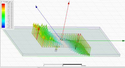
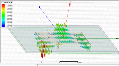
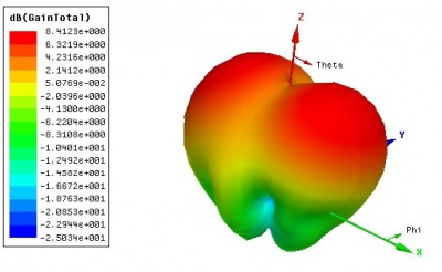
A dual-band antenna is in the class of resonant antenna, it is resonant when the length is around half wave of the resonant frequency. It has following criteria:
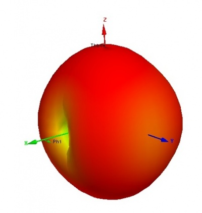
- Broad main beam
- Good impedance matching
- Isolate the human body effect
- Low gain
- Narrow bandwidth
In the design of the patch antenna, the felt is used for the dielectric substrate; and the silver fabric is used for the patch and the ground plane.
Wideband Dipole Antenna
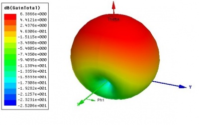
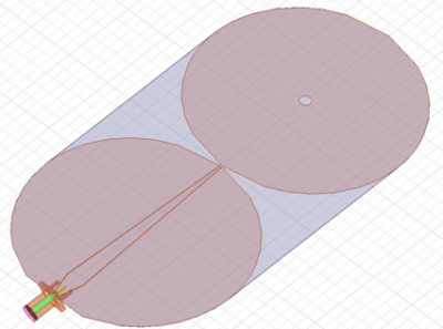
An elliptical dipole antenna is designed with coplanar waveguide transmission line. It has following criteria:
- Wideband (S11 is lower than -10dB from 800MHz to 2GHz)
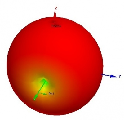
- Omnidirectional
ULTRALAM® 3850 from Rogers Corporation designed to be used as a fabricating material. However, due to the some technique difficulties, the final product has not been produced.
Rectifier Circuit
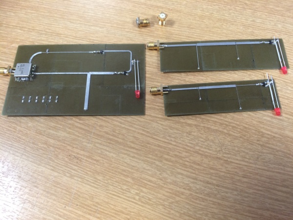
A RF-to-DC rectifier circuit converts collected RF energy to DC electricity. The designed circuit is a half wave voltage doubler circuit with a impedance matching network that matches the rectifier's input impedance to 50Ohms for maximum power transfer or minimum power reflection.
Team
Group members
- Mr Mingzhe Li
- Mr Hung-Kai Mai
- Mr Hanqing Wang
Supervisors
- Dr Thomas Kaufmann
- Prof Christophe Fumeaux
- Dr Yingbo Zhu
Resources
- Bench 22 and 23 in Projects Lab
- Voltage Control Oscillator
- DC Power Supply
- Network Analyser
- Spectrum Analyser
- Oscilloscope
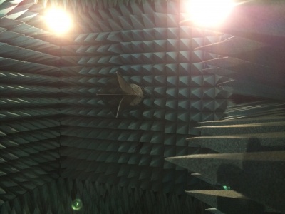
- Anechoic Chamber
- Software
- ANSYS HFSS
- Advanced Design System (ADS)
- MATLAB
References
[1] HF Pues, “An Impedance-Matching Technique for Increasing the Bandwidth of Microstrip Antennas”, IEEE Transactions Antennas and Propagation, Vol. 37, No. 11, Nov 1989.
[2] Sohraby, K., Minoli, D., Znati, T. "Wireless sensor networks: technology, protocols, and applications", John Wiley and Sons, 2007 ISBN 978-0-471-74300-2, pp. 203–209


