Projects:2015s1-16 System Engineering a Trash Collecting Robot
Contents
Introduction
Aim
The aim of this project is to produce the hardware design for an adaptable autonomous robot that is optimised for trash collection, yet capable of completing a wider range of tasks. The informally named TrashBot will be used by a team of researchers from the University of Adelaide's School of Electrical and Electronic Engineering, working in the field of artificial intelligence (AI) architectures. It is their aim to use the completed TrashBot to test their work on a new AI computer known as the Street Engine [1].
Background and Motivation
TrashBot will be a physical testing platform for AI research. It will provide a robot suited to a variety of different applications. The group that will benefit most from the project are the users of the robot, the academic and postgraduate researchers at the UofA.
Currently at the UofA, researchers are developing a new kind of computer processor, the Street Engine. This has been proposed as an efficient processor for real-time and embedded AI systems. Ultimately, a Street Engine will be realised in a custom integrated circuit; however in the expected lifetime of the TrashBot, the Street Engine will be simulated using a conventional computer. The TrashBot will provide researchers an opportunity to develop and demonstrate AI agents for the simulated Street Engine. These agents will be used to evaluate the Street Engine and guide its development. With TrashBot they will provide a demonstration of the benefits and capabilities of the new architecture. Thus the overarching motivation for developing TrashBot is to develop a robot that will facilitate advances in AI at the UofA.
The concept of a trash collecting robot was chosen for many reasons. It is an application of AI that is easily understood by the public and that has clear societal benefits. It is a task that can be constrained to be manageable at the beginning, for example by limiting the kinds of trash collected and simplifying the environment in which the robot operates. However, the unconstrained task of collecting many kinds of trash in a complex human environment, will require advanced AI and is an appropriate challenge for long-term research. To perform this task the robot will require physical capabilities that are useful for other tasks. This means that the robot hardware can be repurposed easily for other applications and hence provide a greater research benefit to the UofA.
Method
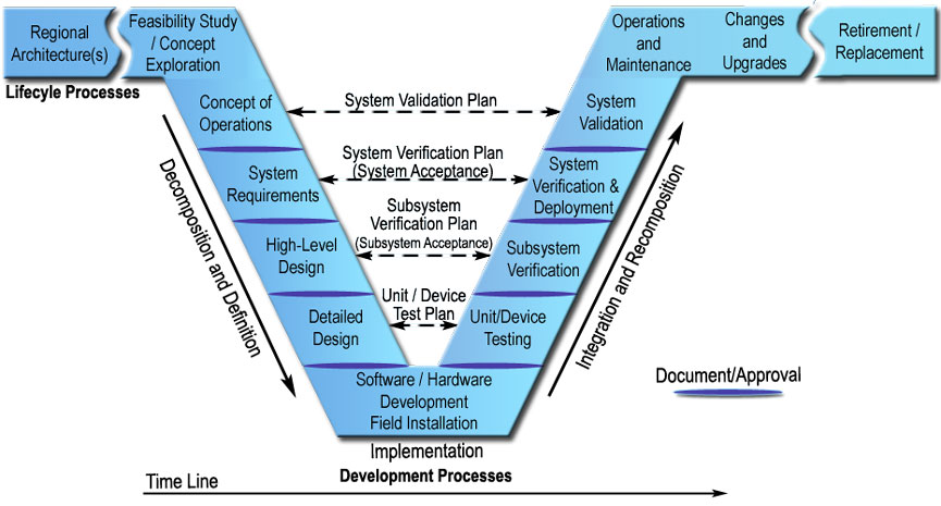
This project the system engineering management method is being applied throughout the project lifecycle. System Engineering is a broad and comprehensive field which integrates the inputs of a range engineering disciplines in order to achieve the realisation of successful systems. Based on the minimisation of risk from common errors; it provides a solid, systematic strategy for the breakdown and development of large, complex projects [xx]. At the core of the system engineering process is the V-model, which can be seen in Figure 1.
There are four important stages before heading to the implementation development processes and those stages are briefly described below:
- Concept of Operations (ConOps)
The ConOps is a foundation document that configures the overall robotic system and state the technical for the project. The ConOps will be the fundamental of technical contributes of this project, which is proposed to convey the developed system high-level views that can be understand by all stakeholders.
- System Requirement Document (SRD)
The system requirements document continues on from the concept of operations document to produce system requirements based on stakeholder needs.
- System Architecture Document
The system architecture document will be a primary work undertaken by our team, and is effectively a comprehensive high level design of the system. It will show with a high level of abstraction how we plan to implement our system and meet requirements. It will also outline the behaviour and structure of the system.
- Detailed Design Document
This document will extend on from the high level design document and will give greater detail into what parts are required, and the operation and integration of the system. This document will serve as a guide for students continuing the project next year.
Following the V-model as part of the system engineering process, which has great advantages for project development in minimisation of project risks, quality of deliverables, minimisation of cost and communication with stakeholder aspect.
Project Team
Students
- Sebastian Roschi
- James Millett
- Sam Bahrami
- Jason Brodie
- Shiwei Sun
- Junxiong Zhao
Supervisors
- Dr. Braden Phillips
- Assoc. Prof. Michael Liebelt
Robotic System
Robotic System
- Structure
The structure system makes up the skin and bones of the robot. Its job is to hold the robot together, and ensure all of its components are protected. Our design uses an off-the-shelf 4WD All Terrain Enclosed Heavy Duty Robot Platform that is built to be strong and durable, with the option of an upper deck for increased mounting space.
- Movement
The movement system acts as the TrashBot’s mode of transportation. It uses a differential steering system consisting of four geared motors with one on each wheel. The motors are capable of producing up to 2.25 Nm of torque and 122 rpm each, producing a top speed of 3.89 km/h. Making use of the four individual motors and a set of large wheels, it has the ability to tackle all types of terrain while retaining a high degree of manoeuvrability.
- Power
The power system was chosen to encapsulate all of the energy and power distribution components of the TrashBot system. This includes wiring of components to receive power, how energy will be stored, how voltages will be converted for the different internal components and how power will be cut in an emergency. Our design uses commercial off-the-shelf components to achieve the requirements, specifically three 12V 7.2Ah lead-acid batteries and a 24V 8A switching DC regulator.
- Sensor
The sensor system was chosen to capture the entire network of sensory equipment used on the TrashBot system. This covers all aspects of the robot’s perception and location including object detection, manipulator state, movement and location, fault detection systems. Each covers a highly important aspect of the robot’s ability to complete tasks and view objectives.
- Logic & Processing
The logic and processing subsystem contains all hardware to allow proper execution of AI software, object recognition software and any other software modules added in future. It also contains the communication lines between all other hardware in the robot, i.e receives information from sensors and sends information to actuators. This includes the network that allows the CMC to control and monitor the robot's operation. The major components of this system are a Programmable Logic Controller (PLC), On-board Computer, Software and a Wi-Fi Router.
- Manipulation
The purpose of manipulation system is to imitate the behavior of a human arm to complete different tasks. The manipulator that has been chosen is the Crustcrawler AX-12A Smart Robotic Arm. Making use of its wrist and shoulder joint, it is capable of 300° motion at a 1.36kg lift capacity; enough to handle the task of trash collection with plenty of flexibility for new functions.
- Beacon
The beacon system was chosen to be compatible with the sensor system. As the cost is insignificant the main factors are signal strength, electromagnetic interference, compatibility, and size. The signal strength should be strong enough to cover the design area without interference or interfering with other sources.
- Control and Monitoring Centre
The control and monitoring centre was chosen to perform live communicate with the robot. This subsystem consists a common laptop computer installed with wireless remote control system ,and compatible with IEEE 802.11g wireless network.
- Charging Station
The charging station was chosen to provide long time autonomous ability for TrashBot. The design consideration includes charging effectiveness, size, degree of fault tolerance, and compatibility. For research purpose, charging time should be short enough to allow sufficient time for experiments, and this subsystem should be able to connect to common electricity plug.
System Budget
The cost of the TrashBot system is an important consideration for the project team. The project supervisors have provided an informal budget estimate of approximately $25,000 AUD for the entirety of the TrashBot system. It is the responsibility of the SenSys team to lead the high-level and detailed designs towards a system that adheres to this budget. To ensure that the budget is not exceeded, cost estimates have been produced as the team work on each stage of the design, refining the estimation as the design grows in detail. At this stage the cost estimate for the TrashBot system is as follows:
| System/Subsystem | Estimated Price (AUD) |
|---|---|
| TrashBot > Structure > Movement > Manipulation > Power > Sensor > Logic & Processing |
$10,037 > $2,438 > $527 > $1,000 > 472.69 > $1,270.77 > $4,133 |
| Command and Monitoring Centre | $0 |
| Charging Station | $400 |
| Beacons | $38.53. |
| Total | $10,037 |
The price of the Structure subsystem is yet to be determined as it primarily consists of custom built components. The SenSys team has scheduled a meeting with workshop staff from the University of Adelaide in order to determine the price. The CMC is planned to consist of a repurposed laptop, and as such will incur no additional cost.
Since the project is primarily a research project there is no immediate need for the honours budget allocated to the project team. The budget will either be unused, or go to products to be displayed at the Ingenuity expo. Possible uses include a display model of the TrashBot or a proof of concept for one its internal systems.
Project Management
Timeline
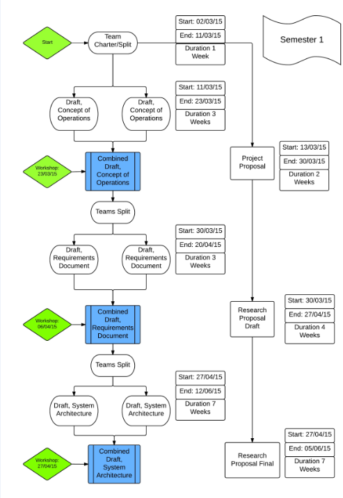
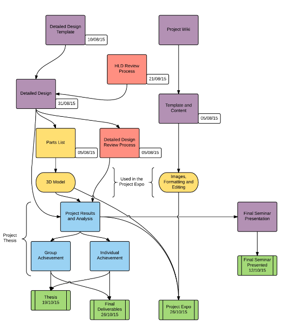
The timeline for this project tracks both the system engineering deliverables as well as the academic deliverables as part of the honours course. This was done to ensure ample time was allocated to both aspects, allowing the team to manage their time effectively to produce high quality outputs with minimal stress.
While a Gantt Chart is normally the standard form of expressing the timeline of a project, it does not succinctly capture the parallel work conducted when the team separates for its deliverables. Instead, the team has produced the timeline for two semesters in the form of a flowchart to ensure these details are clearly presented.
Risk Management
During the early stages of the project, the risk manager and team leader worked together to produce a risk management plan. The document identifies the major risks of the project and presents mitigation strategies for each in the form of a risk register. The risk management strategies used in this project includes: avoiding threat, mitigating risks and accepting risks.
- Avoiding Threat
Team members will attempt to avoid identified project risks by removing the cause of the risk or executing the project in a different way while still aiming to achieve project objectives. Not all risks can be avoided or eliminated, however this will be the first strategy considered.
- Mitigating Risks
Risk mitigation reduces the probability and/or impact of an adverse risk event to an acceptable threshold. The team will endeavor to take early action in order to reduce the probability and/or impact of a risk, as this is often more effective than trying to repair the damage after the risk has occurred.
- Accepting Risks
This strategy will be adopted when it is not possible or practical to respond to the risk by the other strategies, or a response is not warranted by the importance of the risk.
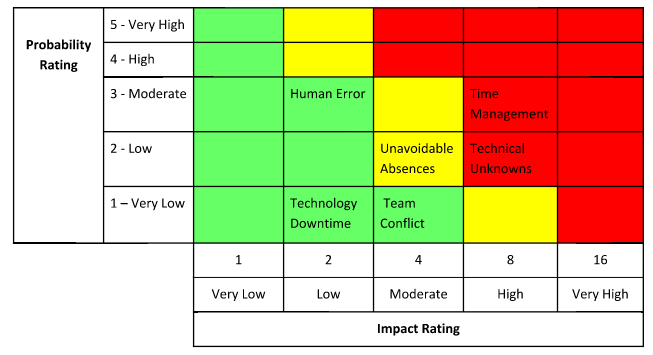
A qualitative process has been used for the risk analysis, where the importance of a risk is given a score based on its probability of occurring and its impact if it were to occur. The importance ratings are summarised in Table xx below, where the colour of the zone indicates the priority of the risk for risk response. The red zone signifies high importance, yellow is medium importance, and green is low importance.


