Projects:2015s1-18 ARM Processor For Digital Systems Practicals
ARM processors collectively forms a family of CPUs. These processors are developed by Advanced RISC machines. ARM processors are based on reduced instruction set computer (RISC). Today, ARM processors are widely used, across different applications, such as in iPhone, tablets and e-readers.
In this project, we were required to design an ARM processor, called disARMed. The disARMed processor is simple, easy to understand, and follows the ARM architecture.
Introduction
Aim
The aim of the project is to aid first year and second year students with their learning of digital systems and computer architecture in Digital Systems courses. The outcome of the project is to create a set of tools as a teaching aid for the laboratories of these Digital Systems courses.
Motivation
The project is being undertaken for the following reasons:
1. The University of Adelaide is restructuring the degrees under the School of Electrical and Electronics Engineering. There will be brand new Digital Systems courses available for the first and second year students under the School of Electrical and Electronics Engineering. A teaching aid is required for the practicals of these courses.
2. These courses uses the Digital Design and Computer Architecture textbook as its primary textbook resource and a new edition of it, which is the ARM edition, will be published this year, on the 1st of May 2015.
The ARM Processor for Digital Systems Practicals project is desired by the lecturers and practical organizers of the Digital Systems courses. The students of these courses will use the products of the project, in their practicals, for a better understanding of Digital Systems and Computer Architecture such as being able to relate the static nature of the instruction mnemonic to the dynamic nature of its execution. The lecturers will maintain, modify and extend the product to suit the specific practical exercises they will make for the courses.
Use Case Scenarios
This section describes the scenarios of how and where the teaching aid will be used.
1st Year Digital System course laboratories
Students will be provided with an example assembly language program. They will simulate the program on the Host PC and observe the execution of the instructions. They can modify the program.
The students will run the example assembly language program on the FPGA board and observe the outcome. There will be specifications provided in the lab which require the students to design logic blocks to connect the disARMed processor with the peripheral blocks such as the LEDs.
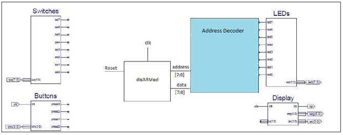
Figure 1.2 shows an example where the students are required to connect the disARMed microprocessor with the LEDs peripheral block with the address decoder coloured in blue.
2nd Year Digital System course laboratories
Second year students will create their own assembly language programs and simulate it on the Host PC. They will observe how each instruction is executed, the datapath each instruction follows, and the change in values in the registers and memory.
The students will download their assembly program onto the Basys-2 FPGA board and run it with the disARMed microprocessor. They will observe the interactions of the microprocessor with the peripheral blocks on board the Basys-2 FPGA board.
In addition, students will explore the Verilog code of the disARMed microprocessor. Students will be given an incomplete disARMed microprocessor where they have to design and implement the missing module.
For example, the microprocessor may be missing the ALU component and students will be required to design their own ALU as shown below (in blue rectangle).
Key Requirements
- disARMed Processor
- Downloader
- Simulation system
- Assembler
System Overview
In this section, we will discuss how the system works,...
System Design
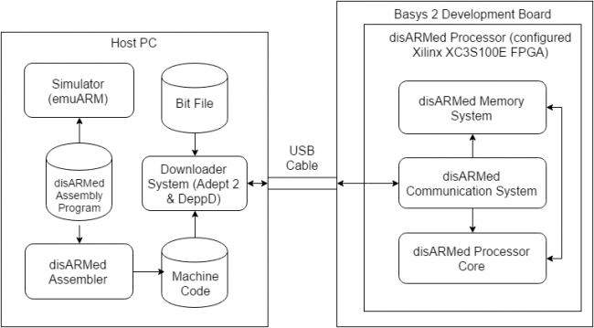
The following diagram shows the overview of the system, as well as how information will flow within the system.
disARMed Processor
Processor Core
The core of the processor is responsible for executing instructions. It is capable of retrieving instructions from the instruction memory, decipher the type of instruction and execute it accordingly. It is also able to store and retrieve data from the data memory.
Memory System
The memory system is the collection of memories required by the disARMed processor. It is used for storing the information required by the disARMed processer core. The memory system is composed of the following memories: data memory, instruction memory and memory for IO devices.
- The data memory stores data.
- The instruction memory holds the list of instructions to be executed by the processor
- The IO memory are registers connected to the IO devices such as LEDs and Seven Segment Display.
Communication Interface
The communication interface is required for receiving information from the Host PC. It performs the following functions:
- Retrieve information from Host PC.
- Decipher the type of information received.
- If control signal is received, forward it to the appropriate system of the disARMed processor.
- If instruction is received, store it into instruction memory.
Downloader System
This system is responsible for sending information to the Basys 2 Development Board.
DeppD
DeppD is an application designed for sending machine code to the disARMed processor. It was created in Java such that it can be used in Windows and Linux operating system.
Adept 2
The Adept 2 application is a PC interface developed by Digilent Inc. This interface is used with Digilent’s programmable board such as the Basys 2. It can be used for configuring the Digilent devices, download and upload data files to and from the device, expand the I/O capability and run tests to confirm the device is operating correctly [Adept].
[Adept] Adept Application User’s Manual, Digilent, WA, 2010, pg. 1-2.
disARMed Assembler
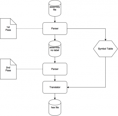
Assembler is the program that reads assembly code and translates it to machine code. Assembly source code can be written with any text editor. The assembler will read the source file and detect any syntax errors and pop error messages correspondingly, then after correction converts correct code to a hex file. Then the hex file will be transferred by the downloader to FPGA board for execution. Both disARMed assembler and downloader are written in Java.
The assembler has two main modules, parser and translator. Parser breaks each assembly instruction into its underlying components (operators and operands and other fields), and translator generates machine code(hex code) according to encoding rules.
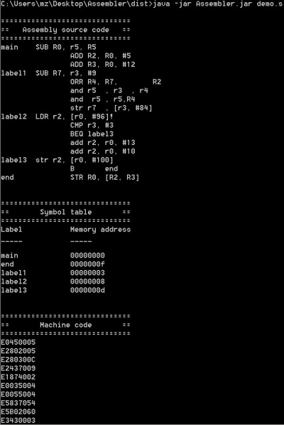
It's packed as a single java .jar file and used as a command line program. User simply type command:
java -jar Assembler.jar <directory/file.s>
If the assembler source code is correctly written, the assembler will display the symbol table and corresponding machine code. Otherwise, an error message will pop to indicate the erroneous code. The assembler will generate a hex file containing the machine code which will then be transferred by the downloader.
emuARM
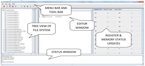
emuARM is an existing open-source ARM instruction set emulator written in java, it reads in assembly code and emulates the behavior of an ARMv5 microprocessor. As can be seen below is the software GUI, user can edit assembly code in emuARM and run it to see the effect on changing registers and memory values.
For more information: http://ieeexplore.ieee.org/xpl/articleDetails.jsp?arnumber=6644358
A simulator is included as part of the system to be created. The simulator will be used for executing the instructions and allowing the user to visually observe what is occurring.
The simulator will take in an input file which contains instructions to be executed. It will have the feature of allowing the students to step through the instructions one by one or executing all instructions without stopping.
The simulator will contain a graphical user interface. The graphical user interface will allow the user to visually observe the outcome of each instruction as it is being executed. It will display the list of instructions as well as highlighting the current instruction being executed, the general purpose registers (r0-r15) and their values, and the memory space and its values.
The GUI will also display the schematic of the disARMed microprocessor and the datapath of each instruction will be highlighted when the instruction is executed. This feature will be selectable under the view tab. A help guide will be available and selectable from the menu tab. It will be used for guiding the users on how to use the simulator. The purpose of the assembler is to translate the assembly language program into a file of a specific format for the simulator and the downloader. The assembler takes in an assembly program as its input. It reads the file and checks for syntax errors. If errors are detected, it will return a message informing the user about it. After reading in a correct input, the assembler will generate a new file which contains the translated assembly instructions. Figure 4 shows two different implementation of the assembler. Method 1 shows that the assembler produces a machine code which will be the input for both the simulator and the downloader. In method 2, the assembler generates two different types of output files. It generates an object file which will be used as the input to the simulator and a machine code for the downloader. The project team will investigate which implementation will be used.
The purpose of the downloader is to upload the bit file and the machine code file onto the Basys-2 FPGA board. The downloader will upload the bit file onto the FPGA board first before uploading the machine code containing the instructions to be executed. This is because the FPGA needs to be configured first before it is capable of executing the instructions.
