Projects:2015s1-73 Improved Electric Micro-Bus Design for Nepal
Project 73, titled Electric Vehicle Design and formerly known as Improved Electric Micro-Bus Design for Nepal, consists of group member Lukas Matthews, Jia Yi Lim, Michael Thompson, and Jinyi Lu.
Throughout 2015, Project 73 memebers have looked at the various elements that combine to make practical and functional electric vehicles. Initially the team focussed on improving the "Safa Tempo", an existing electric powered, three wheeled, ten-seater electric taxi that currently operates in Kathmandu, Nepal. Investigation into the shortcomings of this existing technology and the possible performance increases that could implemented was conducted in the first half of the year. However, due to a lack of funding and the horrific earthquake that struck Nepal on the 25th April 2015, it was decided that implementation of this project was no longer possible. From there the team contacted Dr Nesimi Ertugrul who offered to supply the team with the necessary funding to successfully convert his 2003 Mazda MX5 into an electric vehicle. With the help of Dr Carsten Marksgraf, the team was able to investigate the best possible modification methods and was able to successfully implement an Infineon HybridKit1 - PinFin as well as a Toyota Prius MG2 motor into the Mazda vehicle.
Contents
Background
This project aims to convert an existing internal combustion engine (ICE) vehicle, 1993 Mazda MX-5 into a fully functional electric vehicle. As a part of the on-going project, focus for this year is to implement a 50kW Infineon HybridKIT1 Pin Fin controller into the car. A vehicle controller drives electric motor by converting battery energy into appropriate forms which corresponds to the driver’s command.
The project is highly motivated by the increasing global concern on vehicle greenhouse emission. ICE vehicles source its energy from combustion of fuels, which produces harmful gas such as carbon dioxide, nitrogen oxide and carbon monoxide. As for electric vehicles, chemical batteries are the source of energy and it does not yield any harmful emissions.
Objectives
Functional inverter with Field Orientated Control (FOC)
Phase current monitoring with the use of current sensors
Data logging via CAN Bus
System integration
A vehicle with running wheels, controlled by a throttle
Theory
Overview
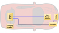
Figure illustrates a general overview of an electric vehicle with the main components in the car. Infineon[1] provides useful insights on the overview of an electric vehicle components. Firstly, the charging system is an AC/DC converter module, which allows car owner to charge up the vehicle batteries from household power. A battery management system (BMS) is included in the battery system for an efficient battery operation. BMS is critical to ensure the battery lifetime, which corresponds to driver’s financial burden. An auxiliary power system acts as a range extender by charging up a 12V power supply from the high voltage battery system. This power is then used to run the vehicle auxiliaries. A controller, or sometimes known as inverter, is also connected to the battery system. This controller converts DC input from battery system into AC output in order to drive and control the electric motor. This intelligently controlled inverter is often designed and programmed to minimize switching losses and maximize thermal efficiency, or even enabling regenerative braking, hence controller is one of the key component for an efficient vehicle. With the commands and AC power from the controller, electric motor converts electrical energy into mechanical torque, propelling the electric vehicle. Lastly, in order to integrate and connect all the individual automotive modules in a vehicle, an internal central communication networking system is usually implemented.
Communication System
A vehicle contains various on-board computing electronic devices to support vehicle efficiency, performance, and user experience. In order to have a closed loop system, data exchange between devices is usually required. This is the part where a vehicle communication network is required. For this project, the group focuses on the development and implementation of a Controller Area Network (CAN) bus. CAN bus is a serial bus communications used to support real-time distributed control system in automobiles and industrial control system. CAN bus system uses bit-serial transmission in twisted-pair cabling as illustrated in Figure 4, enabling communication between CAN devices, or sometimes known as network nodes [2]. Every node on the system receives all transmitted messages. Therefore, identifiers are used for nodes to determine if the messages received are of interest. Twisted-pair cabling is a common practice for CAN bus wiring to reduce noise during transmission by connecting one wire to CAN Low and the other to CAN High [2]. Such method allows data to be transmitted via differential voltage (balanced line) signalling [2]. To recover the signal, CAN Low signal will be inverted, and then added to CAN High signal by the CAN transceiver [2]. Such process will cancel and minimize any noises induced during the transmission process [2]. A pair of 120 ohms resistors are often recommended to be connected on each end of the CAN bus to minimize reflections of signal [2]. However, this is unnecessary for short cable length, less than 40m.
Controller
A controller is connected to the battery system. Controller converts DC input from battery system into a controlled AC output in order to drive the electric motor.
Torque of an electric motor has to be controlled during normal driving conditions to maintain vehicle speed. This can be done by controlling the rotor’s mechanical speed and phase currents. 𝑇=3/2 𝑝(𝜑∙𝑖_𝑞+(𝐿_𝑑−𝐿_𝑞)∙𝑖_𝑑∙𝑖_𝑞)
FOC is the process of controlling the stator current vector in the (d,q) reference frame, based on Clarke and Park Transform.
CANBus
Various on-board computing devices are usually installed inside an electric vehicle. CAN bus is a serial bus communication used to support real time vehicle data exchange in a closed loop system. Lauterbach JTAG Debugger was initially used for such purpose but it is highly prone to electromagnetic interference (EMI) issues. NI USB 8473-s CAN bus device is used for this project. Receive function was developed to read values from controller such as voltage, current, position, and temperature. Software used for the development is MATLAB.
Result
Outcomes for this project are:
Controller is installed into the car
FOC is functioning
Field weakening
CAN bus is able to receive and display readings from the controller
Implementation of controller, CAN bus and cooling system hardware into the vehicle.
Conclusion
For power requirement, at least 20kW rated motor and controller are recommended in order to achieve Dr Ertugrul requirement of driving the vehicle at maximum speed of 70km/h. However, the existing battery pack in MX-5 is insufficient enough to drive motor up to 20kW and is also insufficient to drive the vehicle up to the desired 60km range. Battery pack design is analysed for future battery upgrade. 18650 lithium ion batteries are highly recommended due to the high cycle life, low cost per km, and high energy density. This is a collaborative effort with group member, Jinyi Lu. Testing methodology for motor parameters is also documented for any future drivetrain redesign. Motor parameters such as phase-resistance, phase-inductance, back-emf, diameters are required for closed loop system design.
Analogue-to-digital conversions often require calibration in terms of offset and gain to obtain accurate results. Offset makes sure that the 0 point of digital reading is aligned to analogue reading, whereas gain ensures that the slope of digital reading is aligned to analogue reading. Repetition of calibration process is highly recommended as the offset and gain values are noticeably changed as the controller runs for certain period of time, most likely due to heat dissipated.
A throttle is also designed by using a potentiometer with the output voltage range from 0.5V to 4.5V. This is then connected to the controller as Iw, which is able to control motor speed during closed loop, like a throttle.
Lastly, CAN bus communication is developed due to the EMI issues encountered by JTAG debugger during closed loop tests. Due to time constraint, only functions of receiving data from controller are developed. Send and command functions are recommended as project tasks for future students.
Future Work
Battery pack upgrade
Battery management system (BMS)
Motor upgrade with regenerative braking
Send function for CAN bus
<1>Infineon.com, 'Electromobility: Hybrid Electric & Electric Cars', 2015. [Online]. Available: http://www.infineon.com/cms/en/applications/emobility/hev-ev/. [Accessed: 02- Oct- 2015]. <2>K. Johansson, M. Torngren and L. Nielsen, Vehicle Applications of Controller Area Network, 1st ed. Stockholm: Royal Institute of Technology, Stockholm.


