Projects:2015s1-35 Brain computer interface control for biomedical applications
Contents
Project Instruction
Objectives
The aim of this project is to design a brain computer interface system for stroke patients. The Emotiv EPOC neuroheadset is used to obtain brain signals, while BCI2000 software platform is utilized to design a signal processing software. A robotic hand is designed to support stroke patient’s hand and give feedback. The system should be able to identify users’ intention of moving fingers, and let the robotic hand move as intended.
Motivation and Significance
According to current researches, on average, for every 10 minutes, an Australian will have a stroke. Besides, stroke costs Australian economy 5 billion dollars a year [23]. In this context, designing a brain computer interface system to help stroke patients regain motor control is a great idea, since this may greatly improve their quality of life and also release the burden on economy.
This project is inspired by the previous work of Traeger and Reveruzzi, which is a similar application of brain computer interface system in biomedical usage [1][2], as well as the earlier work of Wolpaw and McFarland [3][4]. Besides, the theory of Neuroplasticity indicates that by imagining limb movements, neuros in brain may create new pathways instead of the impaired ones to reconstruct the connection with motoring muscles, thus regain control of their limbs. However, these researches mentioned above either focus on arm movement, or uses expensive and complicated devices to achieve robotic hand control. Therefore, we intend to design a cost-effective brain computer interface system that can control robotic hand in this project.
With the help of this system, stroke patients can train their brains so as to rebuild the connection between the brain and motor muscles, and in the end regain motor function. Furthermore, the output of this project may help other researches based on BCI systems, and it can be improved to achieve more complex finger movements.
Requirements
The basic goal of this project is to be able to identify the movement of five fingers, while the optional goal is to be able to identify the movement of each finger individually. Besides, the applicator should be able to move continuously as the user imagines to move.
Background
Brain Computer Interface System
A brain-computer interface (BCI) is defined as a communication system that does not depend on the brain’s normal output pathways of peripheral nerves and muscles [5]. Thus, BCI system is the most direct method of communicating between the human brain and a computer or machine. There are three methods of using BCI: invasive method (signal detection device implanted directly into brain), partially invasive method (devices implanted on the surface of brain and inside the skull), and non-invasive method (collecting brain signal by putting electrodes on the scalp) [6]. Invasive and partially invasive methods can provide high quality signals, however, concerning the safety risks of implanting devices in brain, research in invasive methods mainly focus on non-human primates. In comparison, non-invasive methods are widely experimented on human users because it’s far cheaper and safer, as well as more portable.
Electroencephalography
Electroencephalography (EEG) is the recording of electrical activity along the scalp. It is the most studied potential non-invasive interface, mainly because of its fine temporal resolution, ease of use, portability and low set-up cost. The concept of implementing an EEG signal to control a machine existed as early as the 1970s [7], however, it was not until 1999, when the first experimental demonstration was performed, that neuron activity was used to control a robot’s arm [8]. After that, this field has undergone enormous development. EEG research reflects two major types: evoked potentials (transient waveforms that are phase-locked to an event, such as a visual stimulus) and oscillatory features (occur in response to specific events, typically studied through spectral analysis) [9]. Three kinds of EEG-based BCI have been tested in human beings, and they are distinguished by the unique features they use to determine the user’s intent. Among the three, P300 event-related brain potential is mostly stimulated visually, while slow cortical potentials (SCPs) are mainly used for basic word processing and other simple control tasks. The third one is sensorimotor rhythms, which will be used in this project.
Sensorimotor Rhythms
Sensorimotor rhythms (SMR) are well suited for this project, because its amplitudes change with the imagination of movement (also called motor imagery). These rhythms are 8–12 Hz (μ) and 18–26 Hz (β) oscillations in the EEG signals recorded over sensorimotor cortices. Movement or preparation for movement is typically accompanied by a decrease in μ and β activity over sensorimotor cortex [14]. People can learn to control the amplitudes of the two rhythms without any movement or sensation, and use it to move an orthotic device, such as a robotic hand [6][9][10]. It has been proved that the speed and precision of the multidimensional movement control achieved in human beings by SMR method [3][4] equals or exceeds that achieved so far with invasive methods [11][12]. Various BCI designs using SMR method have proved that it is capable of controlling robotic applicators for stroke patients [3][4][13]. Thus, we used it in this project.
Figure 1 shows a typical μ/β rhythm signals. Among these figures, A and B are the topographical distribution on the scalp calculated for actual (A) and imagined (B) right-hand movements and rest for a 3Hz band centred at 12 Hz. C shows an example voltage spectrum for a different subject and a location over left sensorimotor cortex (i.e. C3) for comparing rest (dashed line) and imagery (solid line). D displays the r^2 value for that specific channel [14]. Details will be demonstrated later in this report.
Neuroplasticity
Although research in neuroplasticity is not in the scope of this project, it is still worth introducing, because it is related with the possible future usage of the deliverables of the project. Neuroplasticity refers to changes in neural pathways and synapses due to changes in behaviour, environment, neural processes, thinking, and emotions, etc. According to the research of Byl Nancy [25], stroke patients can regain control of their upper limbs with the training based on the principles of neuroplasticity. Besides, current researches state that BCI system can provide a non-muscular communication pathway between cerebral activity and body actions for people with devastating neuromuscular disorders, such as stroke [9][14][26]. Thus, BCI systems that concentrate on robotic limb/hand control are often designed to support neuroplasticity research.
System Design
Signal Acquisition
Emotiv EPOC neuroheadset is designed for brain signals applications, it can acquire the raw EEG signals by placing its 14 channels and 2 reference channels on the scalp.
In this project, Emotiv EPOC Neuroheadset was used to extract the raw EEG signal of subjects.As the requirement of our project, the team members need to do the offline and online signal processing in the BCI2000. The task (interfacing the Emotiv EPOC headset with BCI2000) have been developed in two parts and corresponding two methods to achieve the final goal.
High level architecture
The high level block diagram of the connection between Emotiv EPOC Neuroheadset with the BCI2000 was designed.First, the raw EEG brain signal from the Headset will be sent to the Emotiv SDK to improve the EEG signal quality.This session will focus on the Emotiv Headset Setup panel. Second, after that, the raw EEG signal will be extracted to the BCI2000. Then, the waveform in the Emotiv TestBench will be as a comparison with the signal in the BCI2000. Furthermore, testing the connection as along as the EEG brain’s waveform in the Emotiv TestBench is same to the waveform in the BCI2000 Source Signal Window. Finally, the connection of the Emotiv headset and BCI2000 will be achieved.
Necessary information
BCI2000 file format and the application of the Emotiv TestBench have to be known. Because these two aspects play a key role in achieving the final goal.After researches, the batch file of the BCI2000 includes a header and the raw brain signals.The extension of the file name is .bat. Besides, the system’s parameters as well as states are included in the header.
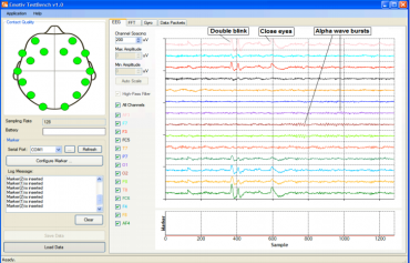
Emotiv TestBench: It is the software of the Emotiv system. It can detect raw EEG signal from the headset automatically and display the real time raw brain signal on the TestBench panel. The EEG suite shows the 14 channels (AF3, F7, F3, FC5, T7, P7, O1, O2, P8, T8, FC6, F4, F8, and AF4) which is corresponding to the 14 electrodes channels of Emotiv EPOC Neuroheadset. In this case, the waveform of the brain signal in the Emotiv TestBench can be as a criteria knows if the raw EEG signal have been acquire to the other EEG signal device successfully . The Brain signal data can be stored in the TestBench with the format EDF which is the standard binary format. This file format is compatible with many raw EEG signal processing software.
Method (for offline analysis)
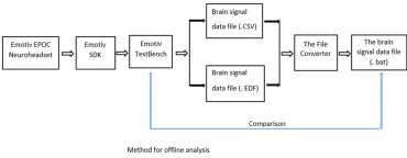
First method(for offline analysis):The method of connecting the Emotiv headset with BCI 2000 source module for the offline analysis was designed.As shown in the flow chart, firstly, the raw EEG signal from the headset will be sent to the Emotiv SDK. Secondly, the trained EEG signal will be sent to the Emotiv TestBench. Then, the EEG signal can be saved as the brain signal data file with the file format EDF (this is the standard file format of TestBench) in the TestBench. Actually, in the TestBench, there is a tool can launch the EDF to the CSV. Furthermore, brain signal data file with the format (CSV and EDF) will be sent to the File Converter to transform these files’ format to BAT (the file format of the BCI2000).Moreover, Compare the EEG signal with the signal in the TestBench. Finally, realizing the interface between Emotiv headsets with BCI2000.
Method (for online analysis)
The flow chart of the online method of acquiring the raw EEG signal to the BCI2000 was developed. In this case, after adjusting the EEG signal quality, the raw brain signal from the headset will be directly extract to the BCI2000 .this can be realized by building the emotiv batch file and set the relative parameter and run the batch file in the BCI2000. Finally, achieving the connection of the Emotiv headset to the BCI2000.
More specifically, based on the literature review, BCI2000 has many contributed modules which can be activated in certain sequence according to the data acquisition equipment or amplifier .This can be realized by using the batch file of BCI2000 and it is located on the installation directory.In relation to this project, the data acquisition device is the Emotiv EPOC Neuroheadset. The Emotiv headset is a contributed source module.
The following procedure was developed for starting the Emotiv headset contributed modules in the BCI2000.
I. Identify the desired paradigm of batch file in the BCI2000.
II. Copy the CursorTask_SignalGenerator.bat, and rename it to the CursorTask_Emotiv.bat.
III. Open the text editor of CursorTask_Emotiv.bat.
IV. Replace the line that refer to the SignalGenerator.exe with Emotiv.exe.
V. Save the batch file in the BCI2000 batch file folder.
Conclusion
The merit of the method 1 (offline): The method 1 for the offline is easier than the method 2 for the online. The key of the success is to find a suitable file converter to transform the file format to the BAT (BCI2000 file format).
Shortcomings: This method is only for the BCI2000 offline analysis.
Advantage of method 2 (online): Suitable for the online and offline analysis.
Disadvantage: In the method 2, build Emotiv batch file is required, it is more difficult than the method 1, because, BCI2000 is really complex and source code is changeable.
Conclusion: These two methods are feasible. Therefore these two methods are applied to the connection of the Emotiv Headset to the BCI2000.
Signal Processing
BCI2000 System
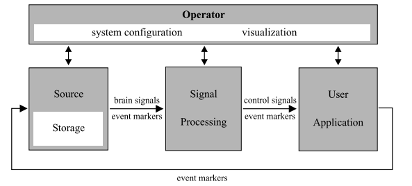
All BCI systems can be divided in to four modules: Source module (signal acquisition), Signal processing module, application module, and the operator module (graphic user interface) [15]. The BCI system in this project is shown on the right hand side.
Signal Processing module
The signal processing module consists of two parts: Feature extraction and Translation Algorithm (i.e. classification) [14]. The figure on the right hand side shows the structure of signal processing module. Signal processing is achieved by inputting the raw EEG signal (which is acquired by the Emotiv headset) into a chain of filters. The output of each former filter is the input of the latter filter.
Basic concepts used in this project
The following concepts are introduced here because they are essential for the understanding of the design.
Trial: a trial is a period of time in which the user is instructed to move finger(s) or to rest his/her finger(s). In this project, a trial usually lasts for 7 seconds. It consists of three parts:
• 1 second of pre-feedback duration, when the instruction is given but no feedback is provided. This period of time is designed for the user to react to the instructions and be prepared to move/rest.
• 5 seconds of feedback duration, when the user moves as instructed and the system provides feedback (i.e. ball movement or robotic hand movement).
• 1 second of post-feedback duration, when the user can see the result of the trial. In this context, it is if the ball hit the target or not.
Inter trial interval (ITI): a period of time between two trials when the user is not instructed to do anything. The user can blink eyes or swallow saliva in this period of time, because these activities are not supposed to be performed during a trial. The aim is to reduce noise in a trial. Details will be illustrated in section 3.7 Application module. An ITI lasts for 3 seconds in this project.
Experimental run: an experimental run consists of a number of trials. In this project, an experimental run include 10 trials.
State: a variable that represents the stage of a trail, e.g. TargetCode == 1, Feedback == 0, etc.
Real-time performance: the data are processed in blocks to enable real-time performance. For each block of data, a control signal is generated. The number of control signals per second can be calculated using the equation: number of control signal(s) per second=(sampling rate)/(block size)
Spatial Filter
The first step after gathering brain signal is to remove noise. There are mainly two types of noise in this situation: noise caused by the distance between the brain and sensor (called spatial noise), and those caused by other human activities, especially facial expressions (hearing, eye blinking, eyeball/ eyebrow moving) in this case. The main aim of spatial filter is to reduce the spatial noise. It is also effective in removing noise that impacts every channel of recorded signal equally. Noise caused by human activities can be minimised by the setting of ITI, when the user can perform these activities without impact the signal quality.
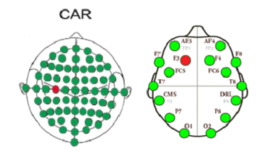
According to the number and position of the electrodes on the Emotiv headset, Common Average Reference (CAR) is used to remove noise. It calculates the mean value once per sample, then subtracts it only from the selected output channels, so as to emphasize feature.
Temporal Filter
Since the feature appears in a specific range of frequencies in the brain wave, transform the signal into frequency domain is essential in this project. The aim of temporal filter is to perform the time-frequency transform. This is achieved by using an autoregressive (AR) filter. The AR filter computes an autoregressive model of input data using the Maximum Entropy Method (MEM) (Burg Method). The output is an estimation of power spectrum collected into bins.
In the context of BCI2000 platform, AR coefficients can be considered as the coefficients of an all-pole linear filter that is used to reproduce the signal’s spectrum when applied to white noise. Thus, the estimated power spectrum directly corresponds to that filter’s transfer function, divided by the signal’s total power. In order to obtain spectral power for finite-sized frequency bins, the power spectrum needs to be multiplied by total signal power, and integrated over the frequency ranges corresponding to individual bins. This is achieved by evaluating the spectrum at evenly spaced evaluation points, summing, and multiplying by the bin width to obtain the power corresponding to a certain bin. For amplitude rather than power spectrum output, bin integrals are replaced with their square roots. [14]
More detailed algorithms about AR, MEM and Burg method can be found in the references [19][20][21]
Classifier
The linear classifier translates the features from AR Filter into output control signals using a linear equation. Thus, each control signal is a linear combination of signal features. Input data has two indices (N channels × M elements, or frequency bins), while the output signal has a single index (C channels × 1 element); thus, the linear classifier acts as NxMxC matrix, determining the output after summation over channels and elements [14]:
In this project, as mentioned in the last subsection, the output of last filter is an estimation of power spectrum collected into bins of a single bin. Thus, we can simply take the bin out from the spectrum of that channel. The parameters can be set as follows: ARFilter’s FirstBinCenter – 0; BinWidth – 3Hz; LastBinCenter – 30Hz. With a bin center of 12Hz, it gives 10.5Hz – 13.5Hz frequency bin of the specific channel.
Normalizer
The normalizer applies a linear transformation to its input signal. For each channel indexed with i, an offset value is subtracted, and the result multiplied with a gain value:
Since the amplitude of brain signal may change greatly during an experimental run, an adaptive normalizer is required. From the previous value of its input, the Normalizer estimates amplitude adaptively to make its output signal zero mean and unit variance. The Normalizer uses data buffers to accumulate its past input according to buffer conditions. In this project, only two buffer conditions are needed, since only the moving and resting of fingers is concerned. This also means only 2 buffers are required. Condition 1 is (Feedback==1)&&(TargetCode==1), when the user is instructed to move (or to imagine to move) fingers, while condition 2 is (Feedback==1)&&(TargetCode==2), when the user is instructed to rest (or imagine to rest) his/her fingers (details about Feedback and TargetCode are explained in 4.7 Application module). Whenever a condition is evaluated to be true, the current input will be recorded in the corresponding buffer. Whenever it comes to updating offset and gain values, the Normalizer will use the data recorded in buffers to estimate data mean and variance. The offset will then be set to the data mean, and the gain to the inverse of the data standard deviation. In this way, the offset and variance is always updated for each block of data going into the system. The buffer length is set to be 10 seconds, which is two times of the feedback duration. This is sufficient to give a good result, as verified by experiments. The update is done when each feedback duration ends.
Application module
The module is designed for two reasons: 1. BCI2000 system refuse to run with any module missing; 2. give the user instructions to move or rest fingers; 3. to test the signal processing module before communication with hardware part.
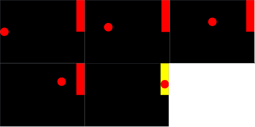
In terms of the change of states in a trial, the state “TargetCode” is used to represent which target shown on the screen. It has three values. TargetCode==1 means target 1 is shown, while TargetCode==2 means target 2 is shown. When TargetCode==0, nothing is shown on the display window. In this project, Target 1 and 2 lasts for 7 seconds, corresponding to the trial time, while nothing is shown on the display window for 3 seconds, which corresponds to ITI. Recall from the spatial filter section, the facial expression plays an important role in causing noises, the ITI is designed to give the user several seconds after each trial to perform un-avoidable activities, like blinking eyes or swallowing saliva. This may help the user to avoid facial muscle movement during a trial without being too tired.
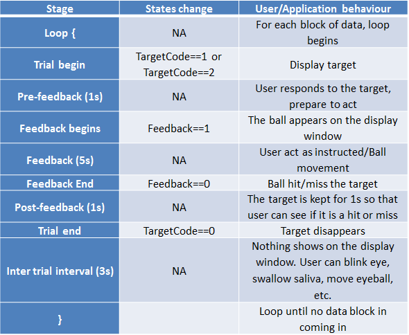
The state “feedback” is labelled at the beginning of a feedback and the end of feedback. The whole process can be described in the table below. Notice that the stages where the background is purple happens in an instance, which is also when the states changes. In comparison, the stages with a yellow background happen for a period of time. (Note: 1s means 1 second in this table.)
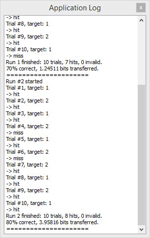
As the experiment runs, the useful information, such as the index of trial, which target is shown, and if it is hit or missed are recorded in an application log. In the end, it provides a summary of the experimental run. A typical application after an experimental run is shown below.
Appconnector
In this project, the communication between BCI2000 and Arduino is achieved by sending and receiving UDP packets. BCI2000 has an in-built method to write states and control signals into a local port or other device. The default setting is to send all the following states and control signal to the Arduino micro-controller, however, the only information needed in this project is the TargetCode, Feedback and Signal. Thus, the information is filtered before transmitting to Arduino micro-controller.
Applicator
High Level Architecture
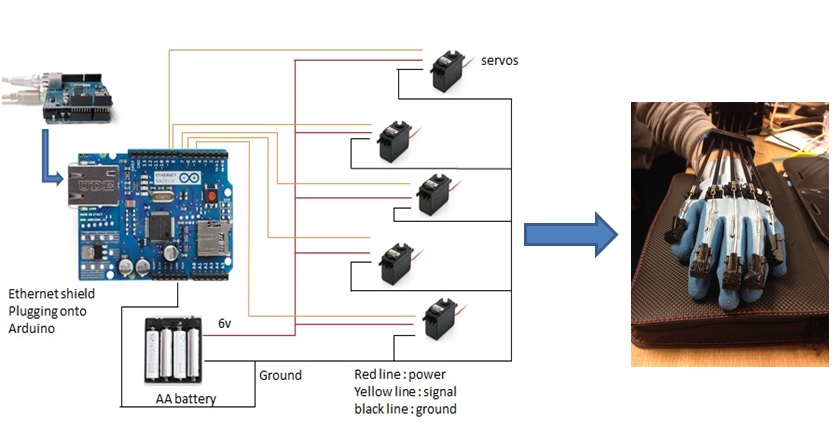
The high level architecture of brain signal transmission can be seen in figure [3] as below. At first, the brain signals will be acquired by Emotive headset and processed by BCI200. After that, the brain signals are transferred from BCI2000 to Arduino Uno with plugging an Ethernet shield by using a crossover cable. Then Arduino as a microcontroller will translate these signals into Pulse Width Modulation signals to control rotation of servos. Ultimately, the servos will drive the movements of robotic glove.
Research planning
What kind of robotic glove design is best for this project?
What kind of motor can be used for driving fingers movements?
How to build a bridge between BCI2000 and applicator?
How to choose components to reduce the weight of applicator?
Design Technology
Glove
Glove is made of soft materials and each finger is driven by a brake cable which consists of a metal wire rope inside and a tube outside. Moreover, the cable should be fixed on the glove and forced to go through whole finger and arm by using a cable guide system. The cable guide system includes fingertips, tube, knuckle guides, and arm guides. Except tube, all cable guides, which are designed by using Autodesk Inventor, are made of 3D printing. Fingertip is a plastic part placed on the top of each finger and this is the only fixed point with cable. Tube is a plastic hose making the cable go through along the whole finger. Knuckle guide is located on the Knuckle of the hand and force the cable to go through the Knuckle.
Servos
Servos are controlled by receiving a pulse of variable width. The control wire is used to send this pulse. The parameters for this pulse are that it has a minimum pulse, a maximum pulse, and a repetition rate. Given the rotation constraints of the servo, neutral is defined to be the position where the servo has exactly the same amount of potential rotation in the clockwise direction as it does in the counter clockwise direction. The angle is determined by the duration of a pulse that is applied to the control wire. This is called Pulse width Modulation. (The servo expects to see a pulse every 20 ms). The length of the pulse will determine how far the motor turns. For example, a 1.5 ms pulse will make the motor turn to the 90 degree position (neutral position). In this project, we can use the Arduino function to decide the position of rotation. And for the requirement, the servos should be moved 12 degree per time when Arduino receive a signal. However, servos cannot give a feedback of the real location to Arduino. Therefore, we use a loop to instead.
When these servos are commanded to move, they will move to the position and hold that position. If an external force pushes against the servo while the servo is holding a position, the servo will refuse to move away from that position. The maximum amount of force the servo can exert is the torque rating of the servo. Servos will not hold their position forever though; the position pulse must be repeated to instruct the servo to stay in position. In our project we choose hk15138 because the torque is strong enough to hold the weight of finger and cable.
Arduino
Arduino Uno is the microcontroller of the hardware system,(it receives signals via UDP shield and translate it into commands to control the robotic hand.Firstly, it has good performance with a reasonable price. Secondly, the applications based on this broad are flexible and easy to use, because Arduino broad can be connected to a computer simply with a USB, and the functions can be expanded by plugging with an external shield. Moreover, Arduino has in-built functions to read the input signals from the devices of data extraction and translate these signals into Pulse Width Modulation (PWM) signals for output to control servos [18]. Last by not least, Arduino provides a free software platform IDE (Arduino Integrate Development Environment) using C language.
Ethernet Shield
Ethernet shield is plugged onto Arduino Uno to receive UPD datagram form BCI2000.UDP is short for User Datagram Protocol and it is a transport layer protocol. Each output operated by an application produce that requires exactly one UDP datagram,which in turn causes one IP datagram to be sent.In our project, the UDP datagram is transferred between a laptop and a microcontroller Arduino Uno by using a crossover cable to connect the laptop and the circuit board. The main reason for us to use this protocol is that this is the only communication method BCI2000 supports. Although UDP has the disadvantage of being not totally reliable, as our experiments show, the data packets are seldom missed, duplicated or discarded. Thus the drawback is negligible in this case.
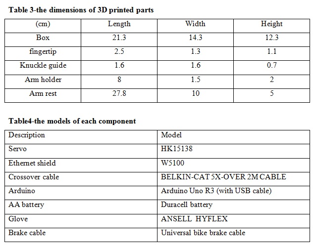
Parameter of applicator
Project Outcomes
the basic goal of this project is to identify the movement of 5 fingers, while the optional goal is to identify the movement of each finger individually.
Basic requirements include using Emotiv EPOC neuroheadset as the signal acquisition device, using C++ language for programming, and developing a portable small size robotic. The designed system meets all these basic requirements.
Signal Processing Testing
For the basic goal, the software part has been tested using the application module mentioned before. Since the step by step result and how parameters were chosen has been discussed in detail in Section 3, only the parameters themselves and the test result of the system is presented here.
The main parameters used are listed below.
• Sample block size: 4/8
• Number of channels used for spatial noise removal: 14 (all channels)
• Spatial filter output: channel F4
• Frequency bin width in AR estimation: 2Hz
• Central frequency of the bin: 10Hz
• Model Order of AR model: 16
• Evaluation per bin: 15
• Window length of spectrum estimator: 500ms
• Number of test subject: 1 (the only available one, also the author of the report)
According to the test results based on 100 trials, the system is able to detect movement of five fingers. These parameters can give 75% accuracy in ball hitting targets for actual fingers movement/resting, and 70% for imagination of movement/resting. With other parameters the same but block size set to 8, the system achieves 73% accuracy in ball hitting for actual movement/resting and 69% for imagination of movement/resting. For real time performance, there is no noticeable time delay in this system.
The results of block size 4 experiments are presented because them achieved the highest accuracy, while the result of block size 8 is shown here because it is used in hardware performance testing. Details will be given in the next section.
Overall Performance
According to the experiments, the smallest degree the servo can turn is 1^°, while the most is 180°. Recall from the application part, the feedback duration is 5 seconds. To make the glove move continuously, the servo is supposed to turn as frequently as possible. With this given conditions, the block size of data processed each time is set to be 8 samples/block, which leads to 16 blocks/second. As the result, the servo turns 16 times in a second, each time for 1°. With 5 seconds feedback, this gives 80° rotation in a feedback session in total. This is why the block size of 4 is not used, because the servo cannot turn 0.5°.
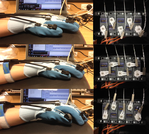
In this context, the 90° point is set as the reference point. Each time the feedback finishes, the glove goes back to the default position, as the first figure below shows. When the user imagines to move fingers, the glove lifts as the third figure shows, while when the user imagines to rest fingers (or just be relaxed), the glove drops.
The table below shows the how long the cable moves when servos turn to different degrees.
As can be seen from the table, only when the user is thinking correctly (i.e. the imagination of movement matches the target shown), the robotic hand moves. Otherwise, it refuses to move.
The real time performance is very good, because there is no noticeable time delay when the system is running. Besides, the system can operate without network connection, since it uses a cross cable to send and receive UDP packets between devices. The hardware part is designed to be light in weight and portable, which gives the system more flexibility in usage.
Project Management
Work Breakdown
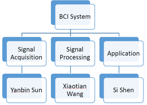
There are three aspects in this project: signal acquisition, signal processing and applicator. All members are working in the whole projects. However, Yanbin sun is mainly focusing on the signal acquisition part (interfacing the Emotiv EPOC Neuroheadset with the BCI2000). Xiaotian Wang is in charge of the part of signal processing. And Sishen is responsible for the hardware part.
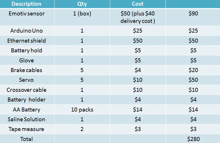
Budget
Risk Analysis
Team
Team Member
Xiaotian Wang
Si Shen
Yanbin Sun
Supervisors
Associate Professor Mathias Baumert
Mr David Bowler
References
The aim of this project is to utilize the Emotiv Brain Computer Interface system to develop and control a robotic limb support system for stroke patients. The Emotiv allows non-invasive recording of electrical brain activity (EEG), which will be utilized for controlling an applicator. The Emotiv also includes a software development kit. Students will acquire skills in signal processing, feature extraction and feature classification. Further, the students will gain experience by designing a basic medical device.
[1] Emotiv, Inc., Emotiv EEG- Quick Set up. [Online] 2013. Available:
    http://www.emotiv.com/eeg/setup.php .
[2] Schalk, G & Mellinger, J 2010, A Practical Guide to Brain-Computer Interfacing with BCI2000, Springer, New York.
[3] Mishra, A 2013, ‘brain computer interface based neurorehabilitation technique using a commercially available EEG headset’, Masters thesis, University of New Jersey’s        Science& Technology, viewed 20 March, 2015, http://archives.njit.edu/vhlib/etd/2010s/2013/njit-etd2013-046/njit-etd2013-046.php.
[4] BCI, Inc., Contributions: Emotiv [online].Available: http://www.bci2000.org/wiki/index.php/User_Tutorial:BCI2000_Tour.
[5] Felton, E.A., Wilson, J.A., Williams, J.C., Garell, P.C.: Electrocorticographically controlled brain–computer interfaces using motor and sensory imagery in patients with temporary subdural electrode implants. Report of four cases. J. Neurosurg. 106(3), 495–500 (2007).
[6] Hallez H., Vanrumste B., Grech R., Review on Solving the Forward Problem in EEG Source Analysis. Journal of Neuroengineering and Rehabilitation, 2007, 4: 4-46.
[7]Mason, S.G., Birch, G.E.: A general framework for brain–computer interface design. IEEE Trans. Neural Syst. Rehabil. Eng. 11(1), 70–85 (2003).
[8]Leuthardt, E., Schalk, G., JR, J.W., Ojemann, J., Moran, D.: A brain–computer interface using electrocorticographic signals in humans. J. Neural Eng. 1(2), 63–71 (2004).
[9]Kirschstein T., Köhling R., What is the Source of the EEG? Clinical EEG and Neuroscience, 2009, 40(3):146-149.
[10]

