Projects:2015s1-46 Channel Measurements for Search & Rescue
The international satellite-based search and rescue (SAR) system, known as Cospas-Sarsat, assists the rescue of people who are in distress by providing satellite-aided tracking and localisation of emergency beacons. This system is currently in the process of major upgrade. New space segments utilising Medium Earth Orbit (MEO) satellite constellation is under deployment, offering several key advantages over the existing solution based on Low Earth Orbit (LEO) and Geostationary Orbit (GEO) satellite systems. Meanwhile, a new generation of emergency beacons is being defined. As an emerging technology, studies on its effectiveness are required to support the ongoing development of the new SAR system. A recent study conducted at the Institute for Telecommunications Research (ITR) has provided initial measurement of the system that demonstrate improvement in its performance. However, a strong signal strength variation in the transmission channel was observed and the cause of the variation remains unresolved. This document proposes a research project to further study and characterise the signal channels in the next generation SAR system. In collaboration with ITR, the project team will conduct a series of field trials and channel measurements. Quantitative data will be obtained to test several hypotheses on the channel characteristics.
Contents
Project Introduction
Aims
The Cospas-Sarsat group is currently developing a second generation search and rescue system. Emergency distress beacons are used to transmit a signal to satellites. The satellites relay the signal to ground stations and the time of flight is used to localize the beacon. First generation systems use low earth orbit satellites and a narrow band waveform while second generation systems use medium earth orbit satellites and a wide band waveform.
The purpose of this project is to characterise the channel for the uplink, i.e. the UHF channel from the beacon to the satellite. Initial measurement by ITR showed strong variations in signal strength that could be caused by antenna patterns, multi path fading, or atmospheric effects from the ionosphere. The student(s) is/are expected to work with software defined radios and our satellite ground station to conduct field trials and process the results.
Background
COSPAS-SARSAT System Overview
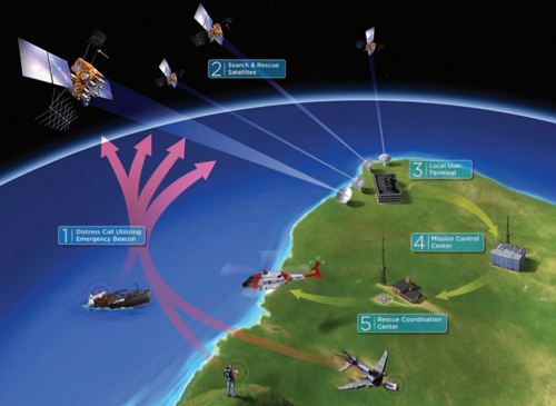
The Cospas-Sarsat system consists of space segments and ground infrastructure. The concept of operation is shown in below picture of COSPAS-SARSAT System Overview. When an emergency situation occurs, a distress beacon device on board aircraft, ships or equipped by individuals is activated to transmit an emergency signal. The signal is then received by satellites, and in certain case, processed on-board, and then relayed to the nearest ground receiving station known as Local User Terminal (LUT). The LUT processes the received signal and sends an emergency alert to the Mission Control Centre (MCC). The MCC then forwards the alert to a Rescue Coordination Centre (RCC) which is responsible for contacting the appropriate rescue authorities within the region. At last, the appointed rescue forces are sent to the emergency location to complete the rescue mission.
Satellite Constellation for Search and Rescue
In terms of satellites, the present system uses LEO and GEO satellites while the next generation system uses MEO. These satellites differ by their orbital altitude, i.e. their distance from earth. Looking at picture, close to earth in the blue region is low earth orbit, followed by medium earth orbit in green. Further away is high earth orbit shown in red. Between the high and medium orbit is the GEO. In the far end of this path is the moon. In the present system, LEO satellites detect beacon locations based on Doppler Effect. However, due to its close distance to earth, LEO satellites have very small satellite footprint, the area on the earth surface that a satellite covers. GEO satellites, on the other hand, offer a large footprint. GEO system must rely on external sources such as GPS to provide location information. In the next generation system, MEO are proposed. The MEO satellite systems offers larger footprint than the LEO satellites and hence fewer satellites needed, and at the same have relative small transmission latency. It provides a true global coverage and near instantaneous detection. In this system, the location information either encoded in in the beacon itself from others sources or obtained by based on the frequency of arrival\time of arrival techniques. The cospas-sarsat plan is to deploy SAR payloads onto existing navigation satellite systems orbiting in MEO, including the GPS satellites and its European and Russian counterparts, Galileo and Glonass.
Related Work
A previous study was conducted in 2014 by the Institute for Telecommunications Research and Honeywell Global Tracking. In this study, MEOSAR satellite orbit and link modelling was performed. A simulation framework that involves a wide band second generation beacon prototype and its receiver algorithms was implemented. Using this framework and the ground satellite infrastructure in ITR, a series of field trials of SGB with MEOSAR were conducted and measurements of the signal transmission channels were performed. The results obtained from the field trials demonstrated the expected performance improvement of the new SAR system and provided quantitative measures of the system characteristics[11]. The results led to a report submitted to the Cospas-Sarsat Joint Committee with recommendations for its further development. In these field trial results, a few issues were revealed that remain unresolved and require further exploration. In one of the trials, a three-hour recording of the downlink signal relayed by the MEOSAR from a test beacon set up as part of the trial was obtained and processed, in which significant variations in the signal strength started to appear from certain point in time. Based on another observation in the same data that as the SAR signal strength fluctuates, the interference level in the channel remain mostly constant, an assumption was therefore made that the source of the variation results from the beacon-to-satellite uplink[12]. The reasoning was that if the source were in the satellite-to-ground downlink, the interference level would have been affected as well. While a few theories were suggested, the root cause of the signal strength variation has not been definitively proven. This issue will serve as the basic research question for this project and a starting point to study and characterise the communication channels in MEOSAR system. The main output of the ITR study and field trials, including a number of written reports and software packages as part of implementation for the simulation framework, were obtained under a confidentiality agreement and will assist the development of this project.
Hypotheses
For the defined research problem, a number of hypotheses were made, providing different factors that are assumed to have an impact in causing the signal strength variation and are therefore potentially key aspects to consider in providing characterisation of the MEOSAR transmission channel. This project will seek experimental evidence to prove the hypothesis and quantify the impact of these factors. • Antenna radiation pattern Radiation pattern is the property of an antenna where the strength of the received signal is dependent on its direction with respect to the antenna. Changes in the elevation angles of satellite as it orbits over the transmission antenna of beacons is likely to cause variations in the uplink signal strength which will eventually be reflected on the downlink. On the other hand, improper choice of antennas type or placement of the physical antenna may have resulted in non-optimal signal reception in the transmission environment during the previous field trials. • Multi-path fading In a real transmission environment, signals may reach the designated receiver via different paths due to factors such as reflection and refraction caused by obstructing objects and transmission materials in the environment. These factors potentially have the effect of causing destructive interference of signal leading to signal strength fading. • Faraday Effect in earth ionosphere Faraday Effect is the interaction between light and a magnetic field in a medium which causes rotation of the polarisation of the transmitting signals[13]. The ionosphere of the earth contains a large amount of free electrons that contribute to Faraday Effect. As a result, when the beacon signals pass through the ionosphere, its polarisation may alter and no longer match the polarisation of the receiving antenna, effectively lowering the strength of the received signal.
Research Methodologies
Software Simulation
Software simulation of the SAR system will be performed to obtain theoretical and predictive data for the SAR system operation. This will help plan field trials and examine the measured data to be collected. This effort will be assisted by the existing software packages developed as part of the previous ITR project with moderate amount of additional development. The simulated environment will mainly include: • Generation of second generation beacon signals • Simulated signal transmission channel with added noise and interference, including Gaussian white noise, inter-symbol interference and multi-path fading. • Receiver-end processing of signal using SAR receiver algorithms
Field Trials
A major focus of the project will be placed on field trials of the SAR system to gather quantitative measures of the SAR channel and to test the proposed hypotheses. The field trials will be based on a simulated framework to be prepared that involves the below segments. • A test beacon prototype capable of physically transmitting second generation beacons with controlled parameters. • Currently operational MEOSAR satellites selected to receive test beacon and relay to the ground. • Ground satellite facility that is able to capture the relayed signal from MEOSAR.
A number of software and hardware resources and facilities available at ITR will need to be used to conduct the field trials. A SAR trial environment has been established in the previous ITR study. This environment configured and customised with potential development and modification to suit the need for the field trials in this project.
This task needs to carefully prepared and coordinated to meet satellite orbit schedule, availability of ground facilities and any RF regulatory requirements. The project plans three phases of field trials with the below corresponding goals.
Stage 1: Initial trials At this early stage, the goal is to confirm the viability of proposed field trial approach and that the existing software & hardware resources available for field trials are functional. It is also meant to allow the project team to familiarise themselves with the trial process and procedure.
Stage 2: Reproduce previously observed issues Project will replicate the field trial setup and attempt to reproduce the results observed in the previous ITR study including the signal strength variation.
Stage 3: Further field trials At this stage, different field trial conditions and experiment parameters will be designed in a way that each proposed hypothesis can be individually explored. A high-level plan for experimenting with each hypothesis is as the following. ◦ Different antenna types and placement will be considered in trial condition explore antenna radiation patterns. The effect of varying satellite elevation angles along beacon antennas will also be examined ◦ Trials with test beacons placed in surrounding environments that cause multi-path propagation will be conducted to explore its impact. ◦ Ionospheric measurements in terms of signal strength attenuation and polarisation will be attempted to quantify its effect on SAR channel. Such measurement performed concurrently with the SAR channel measurements will be considered to examine any correlation between each other.
Data Analysis
The collected data from field trials will be processed and analysed using Matlab and potentially also GNURadio. The processing will primarily involve decoding of the SAR signals, calculation of signal quality and system performance measures, and visualisation of the results. Analysis of the results will focus on the following aspects. • Satellite link estimation and orbit modelling • Signal strength at different processing stages on the receiver end • Noise and interference • Frequency shift in both uplink and downlink These aspects will be examined in consideration of the setup of field trial conditions and any controlled parameters. The result of the analysis and any observations will then help test the hypothesis proposed and generate other findings along that direction.
Resources and Facilities
This project will be conducted in cooperation with the Institute for Telecommunications Research, where a number of software, hardware resources will be supplied for the research activities involved in the project. These will mainly include the following.
Universal Software Radio Peripheral (USRP)
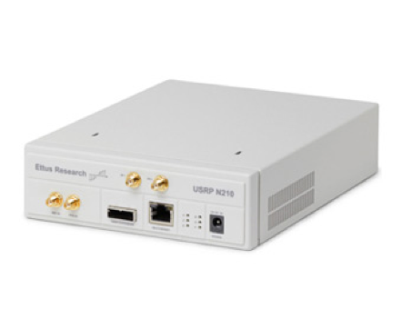
Shown in picture below, USRP is a low-cost software defined radio platform that allows implementation of radio systems in software domain using generic hardware. A radio system can be implemented in a programming language, usually C or C++, and executed on USRP. With a proper antenna connected, the system can either function as a transmitter or receiver. Depending on the model, USRP can either act a standalone unit with embedded CPU, or rely on an external computer connected for processing.
GNURadio
A popular software development tool kit that is often used in pair with USRP. GNURadio supports a model-based radio system design paradigm where digital signal processing function blocks are implemented in C++ programming language and connected at an architectural level through a graphical user interface.
Satellite Ground Station
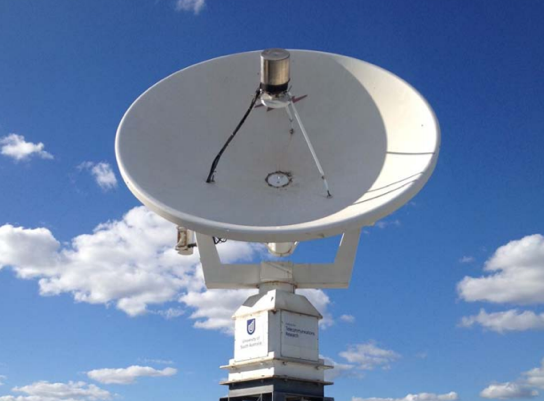
A 3-meter S-band satellite dish, shown in Figure 4, is available at ITR and will provide the capability of tracking a selected satellite and receiving its downlink signals. Additional equipment, such as frequency down-converter, also are available to perform necessary processing on the received signal.
RF Testing and measuring equipment
Abundant electronic equipment such oscilloscope, spectrum analyser etc. will be supplied at ITR to assist the testing and measuring tasks.
SAR Software Package
A set of software packages developed as part of the previous ITR project was obtained. These packages mainly include the following components. • An USRP-based implementation of second generation beacon transmitter, written in C++. This component realises a test beacon generator following the wide-band SGB specification and is to be used with USRP hardware equipped with UHF antennas to transmit test beacon signals. • An USRP-based implementation of a signal recorder, written in C++. This component performs a simple function of saving received RF signal on USRP as raw samples to a file. • SAR receiver algorithms and other analytical tools implemented in Matlab. These components allow decoding of the received SAR signal and provide various signal processing functions used for data analysis. Modifications or extension of functionalities the existing software resource may be carried out to suit the need of the project.
Results
Field trials were conducted to record and examine signals from test beacons through selected MEOSAR satellites.
Ground receiver setup
Main parameters in the ground receiver setup: 3m S-band satellite dish, USRP N210 with GPS timing reference, Signal capture to file.
Beacon Setup
Existing reference beacons located in India ocean and Antarctica. Local prototype beacon includes: USRP, 5W power amplifier, Eggbeater UHF antenna
Burst detection
SAR signal, transmitted as “bursts”, was successfully captured.
Decoding
Beacons from different sources identified. Loss of bursts observed
Band power
Significant increase in interference in SAR band over South Asia.
Conclusion
1. Verified consistent appearing of SAR signal strength variation. 2. Located source of variation to be within the UHF uplink channel. 3. Ruled out factors of antenna pattern, shadowing, scintillation and Faraday effect. 4. Confirmed large regional variation due to population and human activities.
Project Team
Supervised by: Dr Gottfried Lechner (ITR) Dr Matthew Sorell
Team Members: Miss Jiawen Zhang Mr Jilong Zhang


