Projects:2016s1-132 RF Transceiver Design for a Portable Radar
Contents
Supervisors
Dr Brian Ng, Dr Hong Gunn Chew
Students
Benjamin Arthur, Nicholas Aspinall
Aim
This project aims to implement a portable Radar transceiver capable of measuring a target's range and radial velocity. The transceiver shall be implemented into a PCB (Printed Circuit Board) containing RF and analogue subsystems and audio input/output to a computing system for processing and display. The system shall have a range resolution smaller than 2m and a range of approximately 100m for a target with a radar cross section of 1m squared.
Results
Transmit System Results
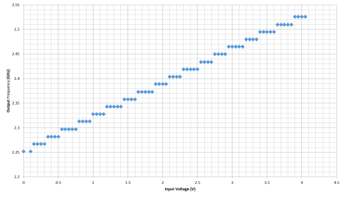
The first testing began on the transmitting system, applying a voltage to the VCO and measuring the frequency and frequency output of the system by connecting the output directly to a spectrum analyser. The cables used for measurements were found to have significant losses, and losses were measured using the RF signal generator at each power and frequency measured from the transmit system.
The transmitting system consists of the power amplifier and bandpass filter. From pre-calculations, the expected transmit power is 14 dBm
For the bandwidth of 2.4GHz to 2.5GHz, as required for this system, a minimum voltage of 2.1331V and a maximum voltage of 3.5803. Hence the transmission signal is a 50% duty cycle sawtooth wave, with a DC offset of 2.1331V, an amplitude of 2.8944V and a PRF of 200Hz.
The transmission power was smaller than expected theoretically, comparing to the data sheets, with measurements of 3dB lower power levels than expected.
The variations in power with frequency would be a result of changes of impedance in the transmission due to changes in frequency.
The receive chain was not operational upon fabrication. Testing of the chain with an input frequency of 700MHz and power of -30dBm netting an output power of 5dBm as expected at the amplifier output. Upon visual inspection of the mixer the alignment was off, and attempts to fix this issue were not successful.
PCB Design 2.0
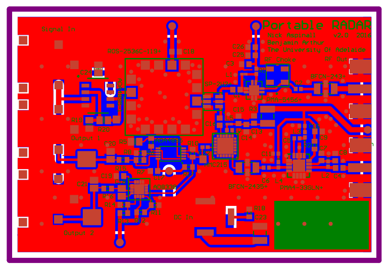
After the manufacture of the initial PCB design, errors in layout were corrected and is present in the final PCB.
The changes are relevant to the practical manufacture and bypassing. The DC power supply has been flipped into it's correct place, and the circular through holes have been replaced with rectangular plated through holes. The capacitor DC input bypassing capacitor has been moved to accommodate for the size of the DC power jack, and so has the capacitor discharge resistor. Thermal relief has been added to the SMA jacks, to assist with soldering. Two more bypassing capacitors have been placed at the transmit amplifier, to better assist with bypassing at that point, particularly noise present from leakage of the VCO. Implemented is an amplifier for the VCO input, decreasing the drive required on the input source.
Conclusion
This thesis outlines the steps taken to design a portable Radar system into a PCB based implementation. The objective characteristics were a range resolution smaller than 2 and a range of approximately 100m for a target with a radar cross section of 1m^2
Through the analysis of different radar architectures and waveforms a stretch processing system was decided upon.The designed system had a theoretical range resolution of 1.764m and a maximum range of 100m.
Although the system was deemed not operational at completion, the transmitter system was operational, tested and voltage waveforms designed for its use. The fabricated system had increased portability comparing to previous works outlined in.
Although the manufacture objectives of the project were not met, the design objectives were and further work and manufacture of PCB design 2.0 will result in an operational system with the referenced above characteristics.
References
[1] G . Charvat, J . Williams, A . Fenn, S . Kogon, J .Herd. RES.LL-003 Build a Small Radar System Capable of Sensing Range, Doppler, and Synthetic Aperture Radar Imaging, January IAP 2011. (Massachusetts Institute of Technology: MIT OpenCourseWare), http://ocw.mit.edu (Accessed 19 Apr, 2016). License: Creative Commons BY-NC-SA
[2] M . Richards, J . Scheer, William . Holm Principles of Modern Radar Vol. I: Basic Principles, 2nd ed., SciTech Publishing, 2015.
[3] B. Mahafza, A.Elsherbeni Matlab Simulations for Radar Systems Design, 1st ed., Chapman & Hall, 2004.
[4] M . Jankiraman Design of Multi-Frequency CW Radars, 1st ed., McGraw Hill, 2007.
[5] J . Toomay, P . Hannen Radar Principles for the Non-Specialist, 3rd ed., SciTech Publishing, 2004.
[6] C. Coleman, An Introduction to Radio Frequency Engineering, 1st ed., Cambridge University Press, 2004.
[7] D . Pozar, Microwave Engineering, 3rd ed., John Wiley & Sons, Inc, 2012.
[8] "Mini Circuits - Global Leader of RF and Microwave Components", Minicircuits.com, 2016. [Online]. Available: http://www.minicircuits.com/. [Accessed: 22- Apr- 2016].
[9] M. Skolnik Introduction to Radar Systems, 3rd ed., McGraw Hill, 2001.
[10] B. Wadell Transmisson Line Design Handbook, 1st ed., Artech House, 1991.
[11] "RF / Microwave PC Board Design and Layout", jlab.org, 2016. [Online]. Available: https://www.jlab.org/accel/eecad/pdf/050rfdesign.pdf. [Accessed: 22- Apr- 2016].
[12] "AD8338 Technical Data Sheet", www.analog.com, 2016. [Online]. Available: http://www.analog.com/media/en/technical-documentation/data-sheets/AD8338.pdf. [Accessed: 5- Jun- 2016]. http://www.analog.com/media/en/technical-documentation/data-sheets/AD8338.pdf
[13] "High Speed PCB Layout Techniques", http://www.ti.com/, 2016. [Online]. Available:http://www.ti.com/lit/ml/slyp173/slyp173.pdf
[14] "High-Speed DSP Systems Design", www.ti.com, 2005. [Online]. Available: http://www.ti.com/lit/ug/spru889/spru889.pdf
[15] "Wireless LANs in the 2.4 GHz band FAQ", www.acma.gov.au, 2016. [Online]. Available: http://www.acma.gov.au/Citizen/Internet/Internet-services/Wireless-local-area- networks/wireless-lans-in-the-24-ghz-band-faqs. 60

