Projects:2016s1-171 All Electric Vehicle for City Use
Contents
Team members
- Azydyana Azlyka Ahmad Azli
- Sachin Joshua Vogt
Supervisors
- Nesimi Ertugrul
- Wen Soong
Introduction
The Electric Vehicle (EV) project is a continuing project at The University of Adelaide. The test vehicle convert from a petrol driven car into an electric car by swapping the engine for a motor and replacing the fuel tank with batteries. At the test vehicle is a 1993 MX-5 with a three phase permenant magnet brushless motor connected to an Infineon inverter.
Project's Aim
The aim for this year's project was to develop the test vehicle to be able to drive in the city. To achieve this the battery would need to be redesigned to handle driving at speeds of up to 70km/h while maintaining a range of at least 70km. The vehicle should be able to climbs hills of 5 degree incline with speeds of 40km/h. In order for the vehicle to drive on the road it must comply with the South Australian Roadworthiness rules. These rule will require a number of extra components that will draw power from the system, reducing the impact that they produce on the system is critical for this project. To increase battery life and maximise the capacity of the system a BMS (Battery Management System) was required for the test vehicle.
Major Require Areas
- Battery system design
- BMS
- Data Logging
- Road Worthiness
Current State:
- Mazda MX5 – NA (MY1993)
- Using 2004 MG2 Toyota Prius Motor
- 50kW Infineon HybridKIT1 Pin Fin
- Using Thundersky 100V 90Ah battery
Project Requirements:
Range
- a range of 70km per charge.
Weight and Size
- The mass of the vehicle must not be more then 1340kg
- The battery's will require to fit in the boot/behind the seat
City Driving
- Capable of reaching 70km/h
- Able to climb 5 degree incline at 40 km/h
- Safety navigate the roads of a city
Auxiliary System
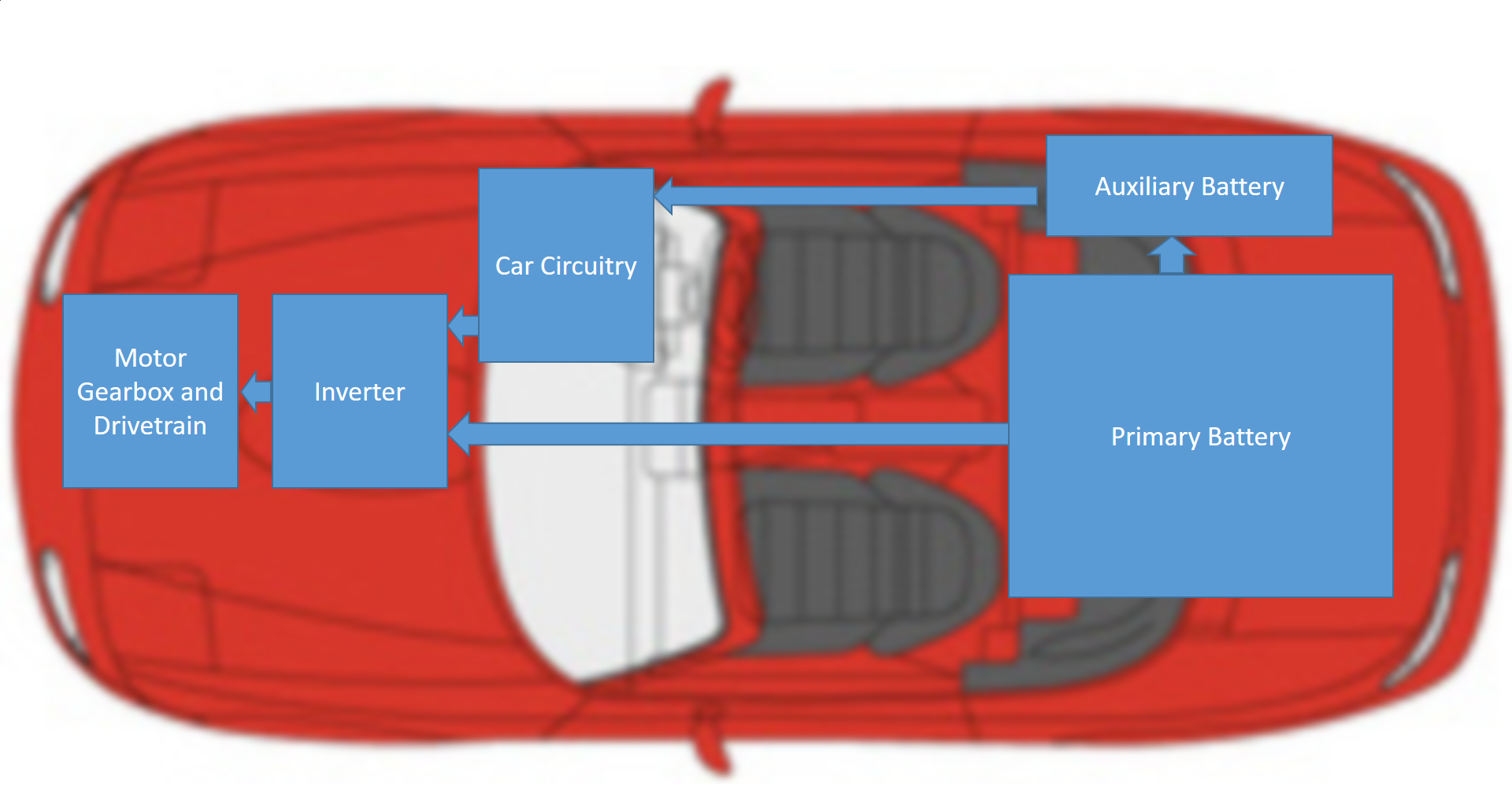
The auxiliary system in looks after components such as the lights, powering the inverter, motors for the headlights, windscreen wipers and side windows as well as pumps for cooling and windscreen washing. A lot of these components are required for the vehicle to be roadworthy. The power draw that they have on the system is a key area that can be reduced to increase the range of the vehicle. To power this system it was decided that a 100Ah deep cycle lead acid battery was chosen. The battery will be powered from a DC to DC converter from the primary battery. In an attempt to reduce power draw the lighting system was replaced with LEDs. Tests were run using the testing diagram to the right and the results are below this was a successful conversion bring the draw down to under 9A for most case. The pump system was reconsidered to be replaced with a lower power model, but a viable solution was not found.
Primary Battery Selection
From calculations based on the drivetrain gear box and inverter the batteries would need to be about 250V have a draw of at least 20A and have a capacity of around 12kWh. From a lot of research a number of options where devised and various pros and cons for them were discussed. The various options can be see in the table to the right. In the end the Thunder Sky Winston WB-LYP40AHA was chosen because it required fewer parts then some of the other solutions. The connectors where screws which meant that welding or soldering would be reduced in the vehicle. Using a step up converter the voltage could be brought up to 500V and the motor would run at rated voltage.
Battery Management System Selection
Battery Management Systems (BMS) is an electronic system that monitors the state of the battery system, sending necessary signals and also helps in protecting the battery from drainage. One of the characteristics of a good BMS is to be able to display accurate data. Next, it must also have high reliability. For instance, monitoring the condition (battery state, temperature and health state) of the battery system at all times and send necessary signals regarding the condition of the battery pack. A BMS must also be linked through a good communication medium to ensure both systems run smoothly. The suggested communication system is CAN bus.
Conclusion and Future Implementations
Based on the research and all the possible implementations that we did to the vehicle throughout the project period, we believe that we have successfully achieved this year’s project aims that are to increase the voltage and capacity of the battery storage system. We managed to cut down the power consumption by changing the normal globes to LEDs for the exterior lightings of the vehicles. The power consumption for all the lights were all basically reduced by 50% after changing the exterior lightings to LEDs. As for the future implementations, we would suggest for the next team to use the Thunder Sky Winston WB-LYP40AHA battery system and pair it up with the Orion BMS. We would also recommend looking in to using a step up converter to bring the voltage to 500V.
