Projects:2016s1-196 Wireless Power Transfer
Contents
Project Team
Supervisors:
- Dr Withawat Withayachumnankul
Students
- Hang Yin
- Matt Reynolds
Introduction
Wireless power transfer (WPT) is a technology that exploits magnetic, electric or electromagnetic fields to transmit electric power without conductors. This project aims to develop a magnetic WPT system for charging portable devices. The system consists of an oscillator, an amplifier, two coils, a rectifier and the load.
Motivation
The WPT technology has been widely used, especially power charging for portable devices, medical implants and electric vehicles. However, the contradiction between high efficiency, small size and long distance has limited the commercial applications of WPT. Current applications have to sacrifice one of these parameters. Designers should adjust these parameters carefully to meet the requirements of a specified application. Suitable coil design and frequency selection can also improve efficiency without affecting size and distance [1].
Objectives
Since the developed system shall be able to reach a balance between efficiency, size, distance and output power, the following objectives shall be achieved:
-The output power shall be more than 100 mW.
-The efficiency shall be greater than 60% at a distance of less than 1 cm.
-The system shall be portable. Its size shall be like a common mobile phone.
Previous Studies
The efficiency of some commercial WPT systems has been tested in several studies. Siddabattula [4] reports that current Texas Instrument WPT system achieves 60% efficiency. According to Perzow [5], EPC-9112, a commercial WPT system developed by Efficient Power Conversion Corp, reaches up to 51% efficiency.
Several studies have been performed to improve the efficiency of WPT. Students of the University of Adelaide [1] revealed the main factors that affect efficiency via simulation, optimised coil design and achieved 61% efficiency at 50cm distance by using 50cm coil diameter. Karalis et al. [6] used magnetic resonance and achieved 40% at 2m distance. Zhang et al. [7] designed a omnidirectional WPT transmitter consisting of three orthogonal coils which can transfer power in 3D space.
Method
The coil-to-coil efficiency is first studied. It is demonstrated in section 1.3.3 that the coil-to-coil efficiency depends on the parameters of the coils, including R_1, R_2, L_1, L_2 and k. A model that simulates these parameters is built in Matlab. Using this model, the parameters of the coils which bring a balance between efficiency and output power are found.
Then the whole circuit is designed and construct. At the beginning, a signal generator was used as the oscillator since it is easy to adjust frequency. After the most efficient frequency was found, an oscillation circuit using 555 timer was designed to provide a fixed AC signal.
Coil Design
Physical parameters of coils include shape, size, distance, material, diameter of winding wire and turns. Since the WPT charger is designed for charging mobile devices, rectangle section solenoid is used. The physical shape of the section of coils is 96mm×61mm to match the size of a typical mobile phone. The distance is set at 1cm (centre-to-centre distance). It is assumed to be the most frequently used charging distance in practice. Enamelled copper wire, which is a common material of coils, is used as winding wire.
The selection of winding wire diameter and turns requires simulation. As simulation parses electrical parameters, there should be a map from electrical parameters to physical parameters. Electrical parameters of coils include R_1, R_2, L_1, L_2 and k, as shown in section 1.3. Wire resistance R_1 and R_2 are proportional to the number of turns. Wire inductance for rectangle section solenoid is proportional to the square of the number of turns [8].
Wire Diameter
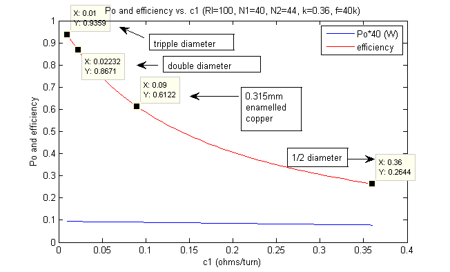
Winding wire resistivity c_1 is proportional to the square of the wire diameter. By changing the value of c_1 in model, the curve below is obtained.
Turns
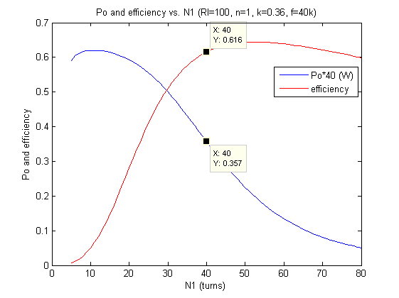
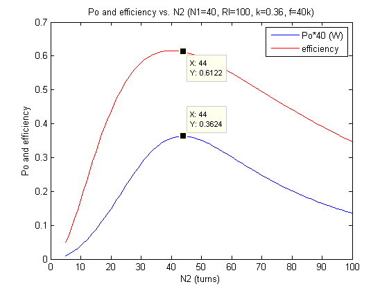
Then the effect of N_1 and N_2 is plotted below.
Circuit Design
The complete circuit is designed as shown in Figure 3.1. It consists of oscillator, amplifier, coils, rectifier, load (R_L) and matching capacitors (C_1 and C_2). The system is powered by a ±5V dual DC power source. A 555 timer is used to generate a fixed frequency AC signal. A class-D amplifier and impedance matching capacitors are used to improve the efficiency and the output power.
Result
The circuit is constructed as shown below.
The results are shown in the table.
Conclusion
This report demonstrates and evaluates the design and performance of the wireless power transfer system. The designing process includes coil design and circuit design. In coil design, electrical parameters are mapped into physical parameters to build a model in Matlab. The effects of these parameters on the system performance are then simulated and the best values of these parameters are selected. In circuit design, the design of oscillator, amplifier and rectifier is explained. Square wave and impedance matching are used to improve system performance.
Experimental testing of the WPT system has proved the positive result of the implementation of square wave and impedance matching. The designing of coils and amplifiers is successful, with an efficiency of 69.4% and output power of 701mW. However, the design of oscillator and rectifier still need to be refined due to the low efficiency they bring.


