Projects:2016s2-216 GPS Receiver Location and Atmosphere Characterisation
Contents
Team members
Man Kit Law
Menghang Jiang
Supervisors
Michael Liebelt
Matthew Trinkle
Project Description
We recently built an FPGA GPS receiver which has been incorporated into a satellite and is due to be launched later in the year.
This receiver sends back raw GPS signal measurements from which it should be possible to determine the position of the satellite as well as properties of the atmosphere based on the signal delays. We have a second copy of the GPS that is almost identical to the one in the satellite and can be used for experimentation.
The main aims of this project are to use the raw GPS measurements obtained from the GPS receiver module (codephase and carrier phase) to determine the position of the GPS receiver and the delay of the GPS signals through the atmosphere. Initially we will be using the measurements from the duplicate receiver on earth. But hopefully we will be able to use the data from the actual satellite early next year.
Objectives
The project’s objectives are listed below.
• Raspberry Pi board
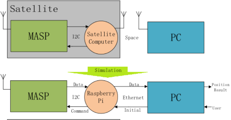
It is used to transmit data through I2C communication between an identical MASP replica board and on-ground PC for testing purpose. The operation between MASP replica and Raspberry Pi board can verify the actual MASP can operate correctly and give us good results before it can be used. Project member Eric Jiang is responsible for this objective.
• Modified Matlab code
Based on the signal sent from MASP replica to PC. The modified Matlab code in PC can do the satellite and receiver position calculations and hence find the position solution. It verifies the signal sent from MASP is correct and MASP can rely on its own signal to find out the position solution in space and hence send back to earth.
Key Tasks
Since SUSat has not been tested yet, the project team is not able to do any experiments using SUSat. In order to test if the MASP is worked or not, one of the supervisors Matthew Trinkle gave us a MASP replica which is identical to the MASP board that in space with exactly same functions.
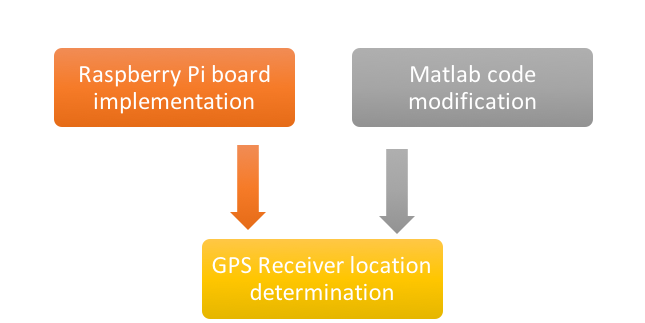
There are three key tasks in this project – “Raspberry Pi board implementation”, “Matlab code modification” and “GPS receiver location determination”. The above two tasks were going to process at the same time. Finally, the task “GPS Receiver location determination” was done by the whole group.
Raspberry Pi board implementation
It is not sure whether the CubeSat is able to have all its applications work well, the performance of the GPS receiver cannot be tested by receiving signals from CubeSat. So a simulation system is built. The simulation system has similar structure of the working principles and data flow (signal transmission) of the GPS receiver system. It will be established and be used to test the effectiveness of MASP, hence the whole on-board GPS receiver system.
MASP
In the system, the Measurement of Atmospheric Species based on GPS Pseudorange (MASP) boards are FPGA boards which were programmed and flashed by one of the supervisors, Matthew, and his assistant, Victor. The MASP board can accept the request from on-ground PC for position determination, read in several (usually 4 to 7) GPS signals from GPS satellites and work out a data packet which should contains enough information for PCs to find out the pseudoranges from the CubeSat to GPS satellites.
On-ground PC The on-ground PC is the user interface of the system. It sends out the request for position determination to the CubeSat, receives the data packet and work out the pseudoranges. By Matlab, the PC can use the data of the pseudoranges and positions of corresponding GPS satellites to calculate out the position of the GPS receiver.
Steps of Operation In the GPS receiver system, the PC will send out a data packet for request of position determination to the Cubsate in space. On receiving the request, the on-satellite MASP board starts to work and then sends the resulting data packet through on-board computer to on-ground PC. The PC reads in the data packet and calculate out the position solution of the CubeSat.
Substitution System for Testing As the CubeSat is to launched in 2017, and further testing of the MASP board cannot be applied before the CubeSat is sent into space. The testing system is created to test the feasibility and performance of the GPS receiver system. The whole testing system is built on ground. An identical MASP board is used to do the same work as the one in CubeSat, and a Raspberry Pi board is installed to imitate the performance of the MASP to on-Board Computer I2C connection in CubeSat, and data transmitting pass from CubeSat to PC.
Matlab code modification
The decoding software in the on-ground PC is Matlab code. This software is provided by a book named “A software-defined GPS and Galileo Receiver”. It contains a lot of scripts and functions to help readers find out how the software process the data.
The given book data block is a raw signal. When this data signal applies to the Matlab code directly, Matlab will then run the acquisition, tracking and positioning functions and hence obtain the location of that data signal automatically. However, the data signal which is sent from MASP board is different from the raw signal. The data signal is going to complete the acquisition and tracking inside the MASP and then send to the PC. Hence, the Matlab code in PC will do the navigation calculation. Since the data format of the book data is different from the data packet back from the satellites, it is impossible to copy the existing Matlab code directly and apply it to our measurements. Therefore, the author will modify the code to fit our needs.
Before the Matlab code modification starts, it is essential to understand how different is the new data format from original data format.
Original data format
Within the book “A software defined GPS and Galileo Receiver”, it contains two raw signals which were collected at different places for use with the GNSS Software Defined Receiver (SDR). These raw signals are composed of three parts which are carrier wave, navigation data and spread sequence. By setting up the acquisition and tracking parameters such as sampling frequency, intermediate frequency and signed character sample format, the raw signal will then upload to satellites from the ground stations. Since the sampling frequency is given, it can keep track of how far away from the 1ms data points the start of the C/A code is. It is very useful in calculating the pseudoranges as the start of the C/A code in unit of samples is known.
New data format
Since the acquisition and tracking are going to be completed at SDK software executed by Raspberry Pi board and MASP in our project, it is not necessary to have raw signal, acquisition and tracking functions in the Matlab code. The new data is stored inside the tracking results which obtained from the output of MASP. This data will then be used to conduct a series of analysis and calculation to obtain the position solution. The new data has at most 8 different data sets for 8 channels. However, for the data packet, the 8 data sets would be stored in only a single array. It has the first bit of each byte set to the navigation message of the first channel and the next bit to the second channel etc. and the final bit to the 8th channel. Notice that the position solution can be found only if four or more satellites are acquired and tracked.
GPS receiver location determination
This task refers to the purpose of the project. After Raspberry Pi board implementation and Matlab code modification are completed, this final task can be processed. Since the decoding software will result in lla coordinate. Comparing the result with the actual coordinate can find out the error of the software to see if the software can be trusted.
If the result is worth trust, it indicates the MASP is operated correctly. Once the MASP in space has been tested, the atmospheric characterisation can start.
Test and Results of Matlab code
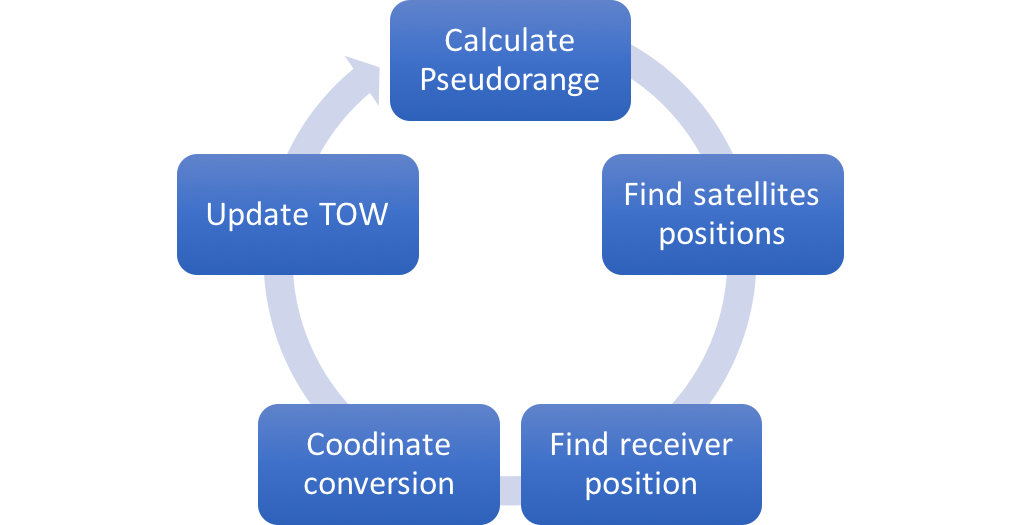
The test process is shown below:
Inside the measurements:
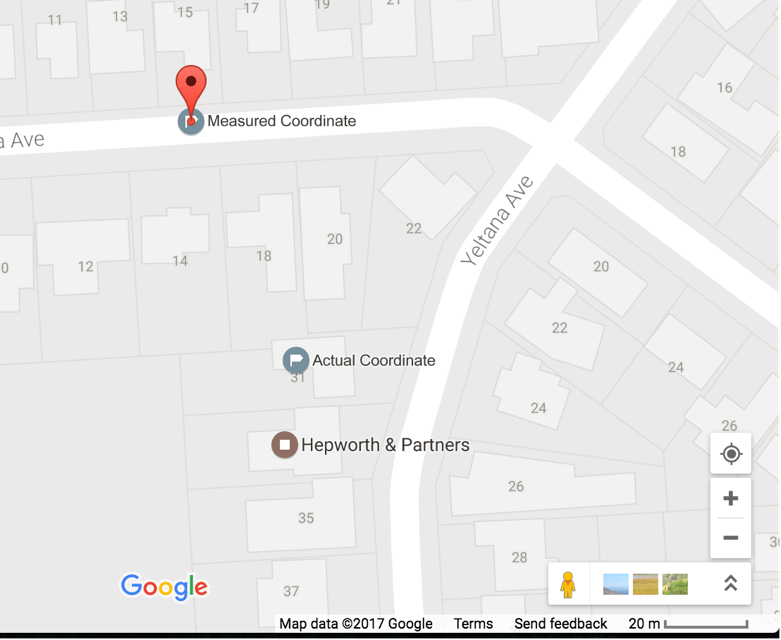
The position solution is the mean value of latitude, longitude and altitude coordinate of all the measurements. Finally, we are going to compare the measured coordinate with the actual coordinate to see the how different is the position solution. The actual receiver location coordinate is provided by the author of data, Matthew Trinkle.
                            Actual Coordinate          Measured Coordinate
  Latitude                    -34.927818                  -34.927288
  Longitude                   138.672724                  138.672440
  Altitude                       N/A*                     214.096601
  *Information not provided


