Projects:2014s2-83 A Testing and Characterising Device for batteries of various chemistries
Contents 1. Project introduction 1.1 Project aims 1.2 Project overview 1.2.1 Hardware overview 1.2.2 Software overview 2. Project result analysis 3. Team management 4. Acknowledgements 5. References
Contents
Project introduction
This design uses the microcontroller to control the system voltage, current and temperature. It can achieve the process of constant current, constant voltage and trickle charge. In sofeware, the design contains different function of each module. According to the work demands of the system, low power consumption and sofeware anti-interference are designed, which ensure the safety and reliability of the system. The design can improve the intellectualization level of the battery charger, realize the control to the charger process more precisely, protect the battery and extend the using time.
Project aims
The aim of the project is to develop a testing and characterising device that can be used with different battery chemistries (primary or secondary (rechargeable)). The device should have the following characteristics: - Mobile, low cost and easy to move around - Useable to characterise batteries that have cell capacity of sub-1 Volt up to 4 Volts - Able to handle up to 6-cell series connected batteries with independent cell characterisation - Able to provide a programmable testing and characterisation waveforms to allow various use scenarios using an easy to use interface, - Able to work independently on its own or when connected to a computer or a tablet - Able to log measured information in a format that is can be stored locally or communicated to a computer using a wired/wireless interface, possibly USB, Wi-Fi or Bluetooth.
Buck converter
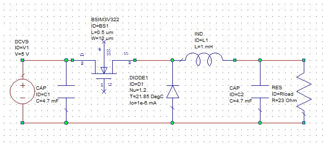
Buck Converter is a step down converter operates with lower output voltage with high input voltage. Varying value of load voltage. The circuit exists in two modes, depending on whether the MOSFET is switched on or off. When the switch is on (short circuited), the supply voltage is applied to the inductor, which causes the inductor current to increase with time. In this state, energy from the source is partly stored in the inductor, and partly delivered to the load. When the MOSFET is switched off (open circuited), the inductor current flows through the diode and the load, causing this current to reduce.
Amplifier
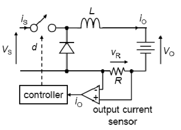
A method of measuring the output current Io and converting it to a value of voltage is required to implement some form of maximum power point tracking using a microcontroller. The simplest method of achieving this is to place a small resistance which is called shunt resistance in series with the negative side of the load, and measure the voltage drop across this resistor. Figure 6 shows an example of how this can be achieved. Given that this voltage will be very small, some form of amplification is required. This can be achieved using a differential amplifier
Balanced circuit
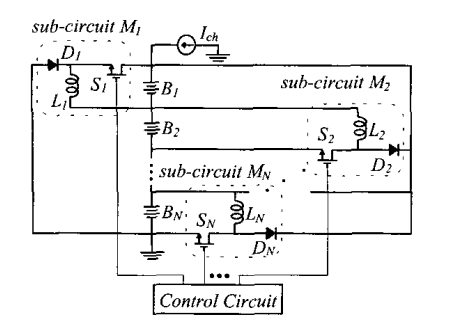
This figure shows a charge balance circuit for N batteries connected in series. The battery bank is charged by constant current. Each battery is shunted by a sub-circuit which is a rearranged buck-boost convertor is battery.
Software Overview
Microcontroller Arduino Mega 2560 Operating Voltage 5V Input Voltage (recommended) 7-12V Input Voltage (limits) 6-20V Digital I/O Pins 54 (of which 15 provide PWM output) Analog Input Pins 16 DC Current per I/O Pin 40mA DC Current for 3.3V Pin 50mA Flash Memory 256 KB of which 8 KB used by bootloader SRAM 8Kb EEPROM 4Kb Clock Speed 16MHz
Project result analysis
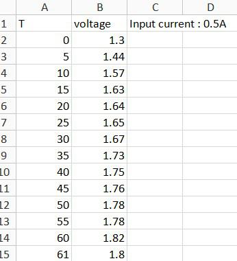
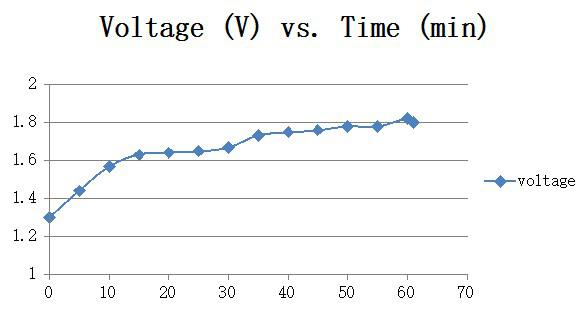
The Ni-Cd battery using here is 1000mAh. Hence when the charging current 1A, it will take about 1 hour to finish the charging. In the experiment, the terminal method is using the negative delta V( NDV) that means when the voltage of the Ni-Cd battery has began to drop the charging will stop. NDV is the recommended full-charge detection for “open-lead” nickel-based chargers. NDV offers a quick response time and works well with a partially or fully charged battery. When inserting a fully charged battery, the terminal voltage rises quickly, and then drops sharply to trigger the ready state. The charge lasts only a few minutes and the cells remain cool. NiCd chargers based on the NDV full-charge detection typically respond to a voltage drop of 10mV per cell. To obtain the needed voltage, the charge rate must be 0.5C and higher. Slower charging produces a less defined voltage drop, especially if the cells are mismatched and each reaches full charge at a different time. Most chargers combine NDV with a voltage plateau detector that terminates the charge when the voltage remains in a steady state for a given time. For additional safety, advanced chargers also include delta temperature, absolute temperature and a time-out timer. From this graph can be seen that in the beginning of 15 minutes, the voltage of the battery becomes very faster from 1.3V to 1.6V. Then the voltage will increase very slowly to 1.8V. At the end of charging, the Ni-Cd battery will have a very small voltage drop about 0.01V to 0.05V. When the microcontroller has checked the voltage drop it will stop the charging immediately.
Team management
References
1] Park Hae-Woo. Han Chang-Seok Ni-MH battery charger with a compensatorforelectric vehicles [R] SAE 9604477, 1996
[2] Niggemann E .High performance nickel-metal hydride battery for electric and hybrid vehicles[Z]E VS-15.Bruxelles.1998.
[3] K.Hirakawa,A.Measuring and Analyzing Method for Battery Conditions Using a New Field Data Collection system,evsl17,2000.
[4] MAXIM.Datasheet:Stand-Alone.Switch-Mode Li+ Battery Charger,2001.
[5] Omagawa Takuya.Manufacture of Secondary Alkaline Batteries [P].JP 0353461.1991-07.
[6] ZHANGShuyun,SUNJiangbei,HUOZhiming. The serial port communication of the computer and single chip[J]. Chinese Science and Technology Information,2005 (10): 130-131.
