Projects:2015s1-50 Tracking, Herding and Routing by Autonomous Smart Cars (UG)
The aim of this project was to create a system of autonomous smart vehicles, which will be able to interact with each other and move in an area without collision. The autonomous vehicle system has been implemented with the use of the official Arduino Robot platform, as an actual “Smart Car” is too large of a project to undertake, therefore a compromise has been made. "Autonomous" is defined as power for self-government, or, having the freedom to act independently. Therefore an autonomous vehicle can be known as a "driverless car", "self-driving car" or a "robot(ic) car", as it does not require any human conduction. Autonomous vehicles operate by using a wide range of technologies to allow them to sense its surrounding environment, avoid collisions and to navigate itself to the destination.
Contents
The Team
Team Members
- Benjamin Riches
- Christopher Bouras
- Michael Cheung
- Tidasa Tennakoon
Supervisors
- Prof Peng Shi
- A/Prof Cheng-Chew Lim
Background
Transportation is an essential part of our everyday lives. Unfortunately there are an increased number of accidents resulting in injuries and fatalities on the road. Countless road safety research reports all reach the same conclusion that the major factor leading to collision on roads, are human factors, whether that be speeding, substance abuse, fatigue or distractions.
To tackle this problem, road safety commissions tend to focus on the driver, however with the technological advances of today, the solution may be less focused on the driver and even eliminating the need for a driver all together.
One way to solve this would be adopting an autonomous vehicle approach, where the autonomous vehicles will adopt object avoidance, communication and efficient movement algorithms to safely get from point A to point B. Some of the advantages towards autonomous vehicles include:
- Fewer traffic accidents, as the vehicle can react faster than a human, as well as having a wider range of sensing.
- Removal of human driver traffic accidents such as speeding, tailgating , distractions, aggressive driving, etc.
- Relieve, reduce stress and pressure for the drivers and the passengers
- In long road trips, it is required that a driver has to stop and rest for a certain amount of time. With autonomous vehicles, they can just rest in the vehicle, while the vehicle can take control.
- Can allow people in no shape possible to operate a normal vehicle to operate an autonomous vehicle, such as the blind, intoxicated, unlicensed, physically disabled, etc.
Introduction
The goals were to create a system where 4 robots could exist, and create formations without interfering with one another. We also devised extension goals which included a ‘Follow the Leader’ approach to basic tracking, and other tasks such as moving in formation. The system was to be designed with keeping the system expandable as a priority, this way, many more than 4 vehicles can be used.
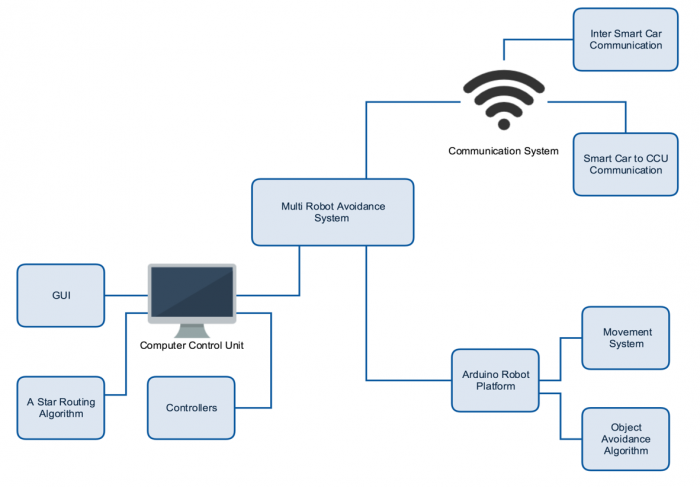
To be able to effectively create the proposed system, three following separate systems were required to be created:
1) Basic Movement System
Comprised of all of the physical systems for robot movement, and all of the related intelligent routing algorithms.
2) Computer Control Unit
Considered the ‘hub’ of operations. This is where commands are connected to, where commands are sent from, and where the user gets a visual representation of the goal movement.
3) Communication System
This system contains all the necessary hardware and software to allow each Arduino robot to receive and send messages to, and from one another or the computer control unit.
This project will demonstrate, at a small scale level, a method of which multiple autonomous robots can interact with each other, and move based on those interactions.
System Overview
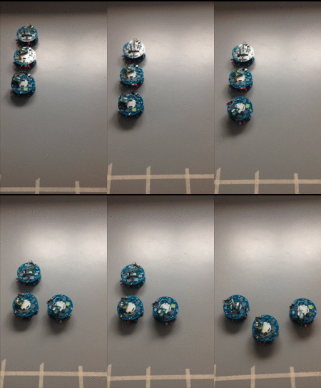
The major design challenge was to develop the three systems and integrate them together to achieve the desired result, and the final product is displayed in Figure 1.
Objectives
The main objective of this project was to develop a system were multiple autonomous vehicles can perform tasks such as formations and basic tracking without collisions. In this system, a command can be sent from a computer, such as "form a line", and from there, 4 smart cars will autonomously move to the required positions to create the formation without colliding with one another. This requires them to be aware of their initial location on the terrain, the initial locations of all other smart cars, and the location of all cars whilst in movement. This will require a communication system between the computer and each robot to be created, and to integrate with the movement system of the smart cars.
A second objective is to create a follow the leader implementation of basic tracking. If time permits, an extension objective that was outlined in the beginning was to keep the system expandable as a priority, this way, many more than 4 vehicles can be used.
Hardware
The Robot
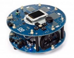
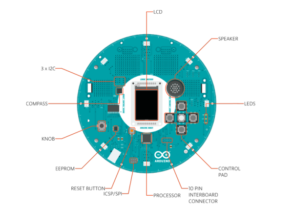
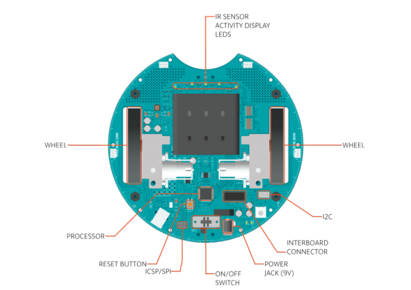
The autonomous vehicle system has been implemented with the use of the official Arduino Robot platform. These robots that are readily available on the market, which made it easier for us as we wont have to design and construct the hardware of the smart car as this would veer away from the scope of our project. The robot is a combination of a control board, which is on the top and a motor board which is on the bottom. Here the control board decides on how it operates. On the bottom of the robot, there is the motor board, which controls the motors. Here it can be seen that the robot motor board contains all the required components to make the robot move, including motors, gearboxes and controllers. The Arduino robot platform has the following key features:
- ATmega32u4 microprocessor
One present on each of the two boards. It is powered by a 16 MHz processor, which is a reasonable amount of computational power. 32kB of on-board flash memory, 2.5 KB of SRAM and 1KB of EEPROM, which are vital for our calculations.
- Pre built movement system
This includes motors, motor controllers, wheels and gearboxes. Also 5 IR line following sensors are included, which could be used as an alternative movement method.
- Miscellaneous
Compass sensor and multiple extension slots to allow additional components (eg. Wi-Fi Shield) to be added
System Details
Communication System
The communication system is vital part of the object avoidance system as it provides the necessary information to be transferred amongst the smart cars and the computer control unit. Wi-Fi has been chosen as the form of communication we have chosen this for the following reasons:
• Wi-Fi shields are relatively cheap and easily adapted on to the Arduino robot platforms; they are come with extensive pre-built libraries to assists with programming.
• Wi-Fi provides the ability to broadcast information, this means multiple devices can receive the information simultaneously.
• Wi-Fi can be made secure to prevent interference from external sources.
• Wi-Fi shields have an approximate range of 100m indoors which is more than adequate for what we require.
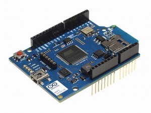
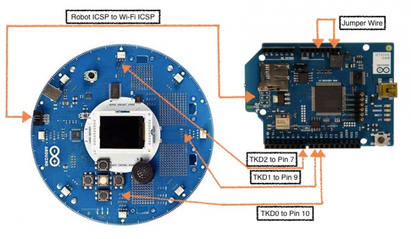
Since the Arduino robots did not come pre-built with any method of communication as standard, the Official Arduino Wi-Fi shield was chosen to provide the robot platforms with communication. Even though the Official Arduino Wi-Fi shield does was the most expensive out of the others Wi-Fi shields tested, this was chosen because of the dedicated libraries and examples provided by the Arduino IDE, online tutorials on how to connect to the robot, and example codes to test with. One very important feature about the Official WiFi shield is the low power consumption. On the platform we have, power is in high demand, and thankfully this add-on board is not power hungry.
In the figure below, the connection between an Arduino Robot and an Arduino Wi-Fi shield has been displayed.
Communication Between Smart Cars
In order for the routing system to determine the optimal route for the smart car to take, it must first know the positions of all the other smart cars in the area. This information is found from the communication system. When a smart car moves, the sensory system described previously will determine the new position of the smart car, this information will then be broadcasted to all the other smart cars in the area using the Wi-Fi communication system. The receiving smart robot will be constantly checking for new coordinates on the Wi-Fi communication network, when it determines that another smart car has moved it will save its new position in onboard memory. Therefore, each smart car will have stored the current position of all the other smart cars in the area and will use this information to avoid collisions.
Communication Between Smart Cars and Computer Control Unit
The computer control unit also plays an important role in the communication network. As previously discussed the smart cars will be communicating their positions to each other, however they will also be communicating their position to the computer control unit as well, by doing this the computer control unit can know where all the smart cars are at all times, this has a lot of uses which will be discussed in the next section. Additionally, the computer control unit will need to send information to the smart cars individually or all at once. This includes issuing commands to the smart cars, giving out initial positions or issuing an emergency stop.
Basic Movement System (BMS)
The basic movement system (BMS) handles any physical moment the smart car will need to make, this consists of moving in a straight line forwards and backwards, performing a 90 degree turn, performing a curved turn and stopping. The Arduino robot already comes pre-programmed with a library to help perform these movements; however code will need to be written in conjunction with this library in order for the robot perform these given movements provided previously.
To achieve our objects, it was required that the robots have to move accurately. However the Robot was supplied with no built-in means for straight line movement, measuring of distance travelled or an accurate turning feature. The built in compass-based turning was, on average, 20˚ inaccurate, which of course was not suitable for our application. Even if both motors were set to the same speed, the existing system was unable to perform a straight movement. Therefore, a movement system, using an encoder for distance and rotation, and a PID (Proportional Integral Derivative) loop for straight line movement was created, which greatly improved the accuracy of which the robot was able to move. This allows the robot to be able to move forward in increments of 25 or 35cm (one grid space) with an accuracy of around 1cm per grid space. It also allows the robot to be able to turn much more accurately, with an average error of around 5 degrees.
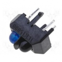
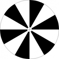
To be able to measure the distance travelled by the robots, wheel encoders were utilized, as replacing the motors with stepper motors was ruled out due to possible hardware damage. The encoders that were used were not the conventional types that can be bought off the shelf, instead it was homemade with the combination of a TCRT5000L optical sensor and a ‘pinwheel’ encoder design, printed on a laser printer. The black and white pinwheel was designed so that 3 transitions was 5cm, which was ideal for our needs. The control circuit was designed to return values of 1 (no reflectivity) and 1024 (100% reflectivity).
The encoder system that was developed was also able to provide accurate turning. Knowing the distance from wheel to wheel, and some basic maths, 1 encoder interval was calculated to be 14˚ degrees. This was perfect for our system which requires movement at angles of 45˚ intervals.
Routing System
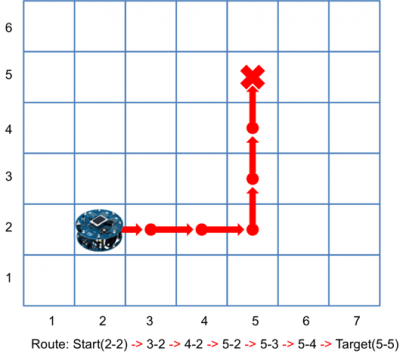
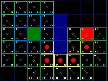
To organise and quantise physical movement, a grid system was created. This allows the adoption of a routing algorithm to enable to robots to intelligently move to a set location. To perform this task, a routing algorithm was designed and implemented, using the A star routing approach. This enabled the robot to move in the 8 cardinal and inter-cardinal directions. The basic routing system is based upon a cost-vector approach, to determine and use the least costly route. The algorithm is able to read each robots location from storage, use the final coordinates to create an intelligent route to that point, of which is sent to the smart vehicles through the use of custom-designed controllers that reside on the Computer Control Unit. An obstacle avoidance algorithm was designed which utilized the A star algorithm for static obstacles, whilst using a prediction of path approach to avoiding dynamic obstacles. The robot then utilizes procedural reasoning to avoid collisions. The avoidance algorithm was developed, however not included in the final version of the software.
Computer Control Unit (CCU)
The computer control unit is the central interface for the other subsystems. It functions by giving a easy-to-use way of controlling the system. It can initialise a variable amount of robots, using the controllers from the Routing system. It will then provide a visual way of setting the starting positions of robots on the grid, and an interactive editor to set and demonstrate the target formation. It will then allow the user to proceed with the task. The Computer Control Unit also can control the ‘Follow the Leader’ code, by allowing the user to select a robot as the leader, and send an instruction to it, causing the others to follow.
The roles of the computer control unit include:
Issuing Tasks to the Smart Cars
The CCU program will have a range of predefined requests the smart cars can perform such as make a shape formation. When the user picks one of these requests the CCU program will first determine the positions each smart car must go to, next it sends out this information plus a status of the task to all the smart cars. For example go to this position and create a square formation.
Up To Date View of the Grid
The CCU will also keep an up to date map showing the current positions of all the smart cars in the grid, this information helps the CCU determine the positions the smart cars must go to, to perform a task. Additionally, other than to give the user a graphical representation of where the smart cars are on the grid, there will be another map that the user can interact with. This map will initially show robot markers corresponding to their current locations. The user will then be able to drag and drop these markers on the map, which will then make the actual robot move to that position in the grid. By doing this, user will be able to create custom routes for the robots apart from the pre-defined formations.
Emergency Stop
To encourage the safety of the project we will have an emergency stop command on the CCU, if the user initiates this command, the CCU will issue an emergency stop to all the smart cars regardless of there current positions or movements. This is to ensure if an error was to occur there was minimal damage to the systems.
Controllers
A central controller handles all messages from the GUI and informs the robot controllers on tasks to perform. Each robot is assigned their own robot controller, each robot controller runs concurrently. Robot controllers provide the robot with access to positions of the other robots, access to the A Star algorithm and communicate any important information from the central controller to the robot. Robot controller and robot communicate using a messaging system. Robot controller has a built in message handler which will know how to deal with every type of message. An example message: IR:CurrentX,CurrentY:TargetX:TargetY.
Project Outcomes
Follow The Leader
In follow the leader mode, one leader robot has the highest priority among all the robots. All the other robots will be following this leader, and the exact path that the leader robot travels. The premise of the robot movements are based on the Snake video game, where the user transmits movement instructions to the leader robot, which are move forward, turn left, or turn right. The constraints in this mode contain:
- User/Leader will not move back (reverse)
- User/Leader will not deliberately bump into other robots
- Robots will only rotate in 90 degree angles
The communication that are utilized will be:
- CCU to robot, where the user inputs the movement instruction which is sent to the leader robot.
- Robot to robot, where the leader robot transmits it's movement instructions to the follower robots.
A short sample of how follow the leader operates is inserted below.
Graphical User Interface (GUI)
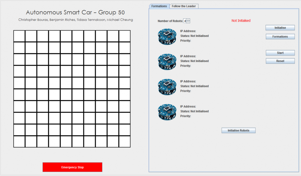
The GUI that has been developed acts as the computer control section of the system. It controls both the formation making, and the follow the leader tasks. In beginning of operation, it will initiate connections to the robots. Then once the connections has been established, it will allow the user to proceed to selecting formations, or starting the leader following code. The user will select the number of robots they want to initialize, then turns each of the robots on, with the first robot turned on, given the highest priority. The GUI contains the grid system as well as the robot details, which would be provided after initialisation has been completed, and is illustrated in Figure 4.
Initialization will be complete, once all the user-defined number of robots has been connected. After around 15 seconds, the robots are connected, and this is shown by each getting an IP address, status and priority. Once all the robots has been initialised, the user can select what ever formation they prefer. They can select from pre-set values, or create their own. Selecting a pre-defined formation will automatically fill the spinner boxes, to create the desired shape, and also update the grid. Pre-defined formations are based on the number of robots available. If the user wants to edit, or create a formation, they can enter in the values and then select ‘Update Grid’ to have that value shown on the grid.
Conclusion and Future Work
Each subsystem worked very well, and passed testing as individual modules. However, when integrating the modules together into one system, errors became prominent. Due to time constraints, we were unable to work out all of the issues, leading to a system which produces a satisfactory result, albeit, unreliably. Our team has learnt from this experience and believe this to be very valuable experience for our future careers as engineering professionals.
References
[1] http://www.robotshop.com/en/arduino-2wd-robot-us.html
[2] http://www.theplaidzebra.com/autonomous-cars/
[3] http://gizmodo.com/virginias-opening-70-miles-of-roads-to-autonomous-cars-1708666160
[4] https://www.arduino.cc/en/Main/Robot
[5] http://store.arduino.cc/index.php?main_page=product_info&products_code=A000058&language=en
