Projects:2016s1-172 Computer Aided Testing of Batteries for Energy Storage Applications
Contents
Project Team
JiJian Fu
Hazwani Yob
Long Tat Li
Supervisors
Prof Nesimi Ertugrul
Dr Wen soong
Introduction
In order to obtain the ability to understand batteries charging/discharging behaviours under various environmental conditions, and obtain their models for further analysis and control,computer aided data logging facilities involving voltage and current sensors, are used to simplify and implement the battery testing. This project designed a battery test system, which is composed by a water tank based temperature control unit, a charging/discharging device, computer controls and data analysis system. This test system is capable to measure battery’s voltage, current and temperature simultaneously between 20~60 . This system is capable to test different types of battery, such as Lead-Acid battery, Lithium-ion battery,Nickel cadmium battery and so on. One of these battery types, Lead-Acid battery, has been tested and the test result are presented.
System Design
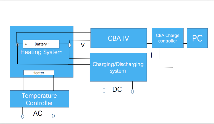
The entire system is divided into three subsystems: The Load Bank system, the Charging/Discharging system and the Heating system.
Figure: Design of battery test system
Heating system
A new designed chamber was built in this project, which is shown in Figure. The water will be used as medium to control the testing environmental temperature since the specific heat of water is higher than the specific heat of air. A larger container covers the smaller container and other elements, and the water would be contained in both containers. A water heater is placed in the inner container for heating the water in the inner container, and a PID controller is connecting to the heater for controlling the temperature of the water. For cooling elements, a water tape and a water pump are placed in the inner container and at the bottom of outer container respectively. The hot water in the inner container will be drained by the water tape and the cold water in the outer container will be pumped into inner container by the water pump. This process causes a water flow that to keep transferring the energy so that to decrease the temperature of the water in inner container. The testing battery will be placed under water totally with a protection such as plastic bag, and two wires from measurement equipment will be connected to the battery. The design is able to control and preserve the testing environmental temperature steadily due to more accurate temperature device PID controller and high specific heat capability of water.
In this project, a 74 cm x 48 cm x 43 cm container will be used for the outer container and a 50cm x 34 cm x 33 cm container will be used for the inner container. As the battery will be put into the water, and also for safety, the purified water will be used in this project to avoid the electrocution. In previous project, the water-ethylene glycol mixture is used since it is a good conductor for heating and cooling, but it is hard to find a large amount of water-ethylene glycol mixture without any supply. In this project, the deionized water will be used, which is provided by chemical engineering in the University of Adelaide. The deionized water is the water that removes all the ions in the water, so there is no impurity in the water to cause electrocution. Anyway, the deionized water is more purify than the distilled water.
Two 12V 120W car heaters, which is shown in Figure, are used to heat the water. Those two heaters will be connected in series to the PID, and the resistance for each heater is 0.9ohms, hence the maximum value of the current would be 12V/ 0.9ohms =13.3 A. However, the power for the heart is 12v x 13.3A=159.6 W, which is excess the power limit of the heater. Hence the maximum value of voltage and current for each heater is 10.9v and 11A respectively, which is 119.9 W. To find the time that the heaters can rise the temperature to a desired temperature, the equation of specific heat Q=mc Δ T = I2Rt is used. The mass of the water mwater would be the length of the inner container times the width of the inner container times the height of the water in inner container times the density of the water. In this project, mwater=50 x 34 x6.5 x 1=11050 cm3 =11050 g =11.05 kg. The specific heat of water c=4186 J/kg c. The temperature difference Δ T is the difference between desired temperature and room temperature (there is no cooling system in this project, so the testing temperature is from room temperature), say 50 degree Celsius for the desired temperature and 20 degree Celsius for the room temperature, so Δ T=50-20 =30 degree Celsius. Therefore, the heat transferred Q is Q=mc Δ T=11.05kg x 4186 J/kg c x 30 degree Celsius =1387659J If the current of the heaters I keeps constant in 11A and the resistance of heaters is 1.8 ohms in series, therefore the time required for heating water to desired temperature is Q= I2Rt => 1387659=112 x 1.8 ohms x t => t=6371 sec=1.77hr
Assume the room temperature is 20 degree Celsius, the time for heating water to desired temperature is shown as below:
Desired Temperature(degree Celsius) Time(hours)
         50                               1.77
         45                               1.47
         40                               1.18
         35                               0.88
         30                               0.59
         25                               0.29
         20                                0
Temperature Controller
A proportional–integral–derivative (PID)temperature controller is used with k type thermocouple for heating system.For the entire connection of PID controller, which is shown in Figure, all setup will be set in a IP66 rated enclosure for safety. A solid state relay (SSR) is used between PID controller and heater. SSR is an electronic switching device that switches on and off in certain case voltage and current conditions. In this case, as shown in Figure, the switch on the top turns on when zero voltage and turns off when zero current, which is connected to a transformer. The bottom circuit is connected to PID controller. As the SSR is required for AC current to switch on and off, a 24v 300VA transformer is needed to connect to the SSR to the heaters.
As shown in Figure, the primary side of the transformer, which is 240 v, is connected to the SSR and PID controller. The secondary side of the transformer, which is 24 V, is connected to the heaters. A k-type thermocouple is connected to the PID controller for measuring the water temperature.
For the entire working process in Figure , the desired temperature is set on the PID controller, and the thermocouple is placed into the water for measuring the water temperature. The water temperature which is measured by the thermocouple is sent to PID controller. Then the water temperature is used to compare with the desired temperature trough the calculation of the PID controller. The switch in the PID controller will be on and send a signal to SSR. If the water temperature is lower than the desired temperature. The switch in the SSR will be on after receiving the signal, so the completed circuit for transformer is done and the current will flow to the heaters. Hence the heaters will start working and heating the water. If the water temperature is same as the desired temperature, the PID will ‘try’ to maintain the temperature and the SSR will be on and off. Hence the heaters will be on and off to keep the water remains on the same temperature. If the water temperature is higher than the desired temperature, the SSR will be completely off. Hence the heaters will stop working and heating the water.
Tested Batteries
Considered to efficiency of the project, project group decided to use two types of rechargeable battery for all the tests implemented in this project. The first one is lead-acid battery while the second one is the lithium-ion battery.
Due to difficulty in the process of project, behind-schedule of the project and safety consideration, eventually only battery with model “Maintenance-Free Rechargeable Sealed Lead-acid Battery 6V 1.3AH” are in used in this project.
Test Analyzing System
The term “Test Analyzing system” is referring to “the section of the battery test system which is used for implement the test and obtain the test result”. Equipment have been chosen and applied in test analyzing system are including: West Mountain Radio CBA IV Pro, West Mountain Radio Charge controller, Standard version CBA software, and iMAX B6AC V2 Balance Charger and Discharger.
West Mountain Radio CBA IV Pro (CBA), is the core equipment of the battery test system, essential for implementation for all battery tests, and result collection for the CBA software. Mechanism to avoid over-discharged is provided from this equipment.
iMAX B6AC V2 Balance Charger and Discharger (iMAX), can charge/discharge battery under safety condition (terminate the process automatically as battery is going to be overcharged/over-discharged). iMAX needs to start the charging process manually. Select the battery type of tested battery, then select “charge battery”, vary the charging rate (current) and number of cells of the tested battery, then press the “start” button for few seconds.
West Mountain Radio Charge Controller (charge controller), is another equipment to prevent overcharge for the battery tests. In this project, charge controller is used to monitor and obtain the current in charging test.
Standard version CBA software (CBA software) is the platform for users to control the test system. All collected results are stored in the software, and are exported in numerical and/or graphical way by software.
In addition, temperature probe “CBA Magnetic Temperature Probe Accessory “will be used for monitoring the temperature of tested battery, to ensure temperature of battery can be varied and controlled by temperature control system.
Approaches
CBA IV Verification and Calibration
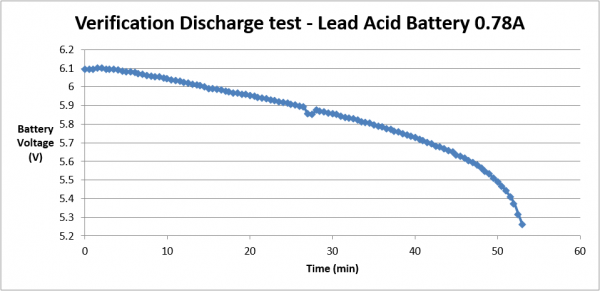
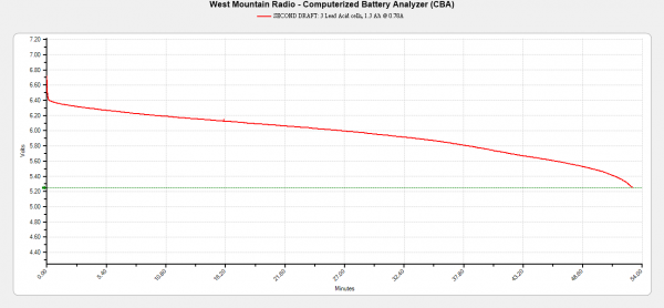
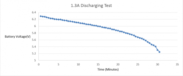
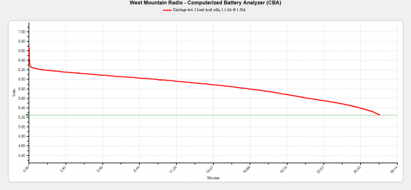
The results obtained from the CBA IV has to be verified in order to confirm the reliability of CBA IV in this project. Therefore the lead acid battery needs to undergo a discharge test using a constant current load tester.Basically the concept of discharging test by using the constant current load tester and CBA IV are almost the same. However, this discharge test is manually conducted by applying a constant current load at 0.78 to the lead acid battery and a multimeter is used to monitor and measure voltage drop during the test until it reaches the cutoff voltage of 5.25V. The voltage value and the time taken are continuously measured and recorded throughout the test. This procedure is repeated with different current values. A graph of voltage versus time is plotted based on the result obtained from this test.
PID Temperature Controller Verification and Calibration
A PID temperature controller would be set up with the heaters in the container. The verification method would be set a desired temperature value on the PID controller and use other equipment such as thermometer to measure the temperature of the chamber, and also measure time required to desired temperature.
Battery Test File:Test
Result
CBA IV Verification and Calibration
From the result obtained, it shows that the CBA IV is reliable to be utilised in this project. This is due to the result from the CBA IV is approximately the same as the result from the constant current load tester and the datasheet.
PID Temperature Controller Verification and Calibration
A thermometer was used to measure the water temperature:
Temperature displayed on PID controller (degree Celsius) Temperature displayed on thermometer (degree Celsius)
                    35                                                            35.2
                    40                                                            40.4
                    45                                                            44.8
As shown on the table above, the temperature displayed on thermometer are approximately equal to the temperature displayed on PID controller, so the thermocouple and the PID controller are accrue for testing water temperature.
A stopwatch was used to measure the time for water from room temperature to desired temperature (the room temperature on the measuring day was 20 degree Celsius):
Desired Temperature(degree Celsius) Desired theoretical Time(hours) Actual measured time (hours)
           50                                               1.77                                           2.56
           45                                               1.47                                           2.03
           40                                               1.18                                           1.75
           35                                               0.88                                           1.05
           30                                               0.59                                           0.68
           25                                               0.29                                           0.33
           20                                                0                                               0
As shown on the table above, the actual measure time is similar to the desired theoretical time at the temperature close to 20 degree Celsius, the actual measure time gets more and more difference to the desired theoretical time.
There are two reasons for the difference between desired theoretical temperature and actual measured temperature. Firstly, the amount of water in the outer container is large, and even covered half size of the inner container. Hence, the water in outer container absorbed the heat and made the heater to spend extra time the heat the water in the inner container. Secondly, the inner container is made in plastics which is not a perfect material for preserve heat.
Two potential solutions were done for trying to reduce the uncertainty or the difference of the heating time. Firstly, the water level in the outer container was decreased below the inner container. As shown in Figure, the water level in the outer container is around the stands of the inner container. Hence, the water would absorb less heat from the inner container. Secondly, the lids for inner container and outer container were put on the inner container and outer container respectively. Therefore, the heat will be better preserved inside the inner container, and effect from outside environment could be reduced.
After two potential solutions were done, the heating time measurement is shown in the table as below:
Desired Temperature(degree Celsius) Desired theoretical Time(hours) Actual measured time (hours)
           50                                        1.77                                        1.95
           45                                        1.47                                        1.62
           40                                        1.18                                        1.38
           35                                        0.88                                        0.92
           30                                        0.59                                        0.65
           25                                        0.29                                        0.30
           20                                         0                                           0
The difference between desired theoretical time and actual measured time is reduced. However, the actual measured time is still not equal to the desired theoretical time. The reason for this is the outside environment might still affect the container. For improvement, a container such as ESKY, which is made in better material for preserving temperature, could replace the inner container.
Obtained results of the test system
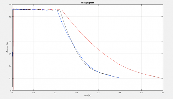
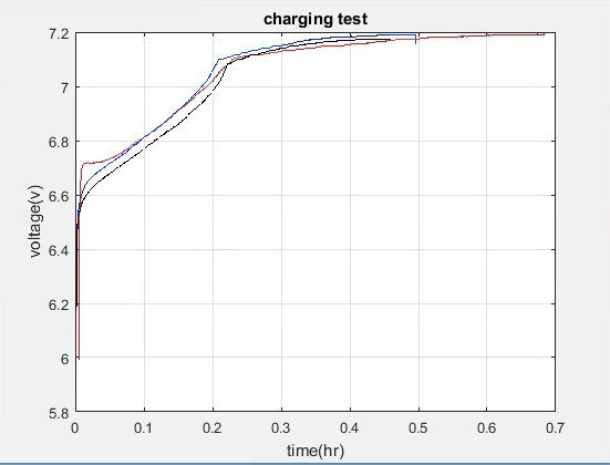
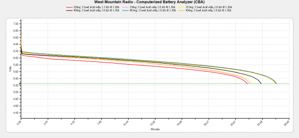
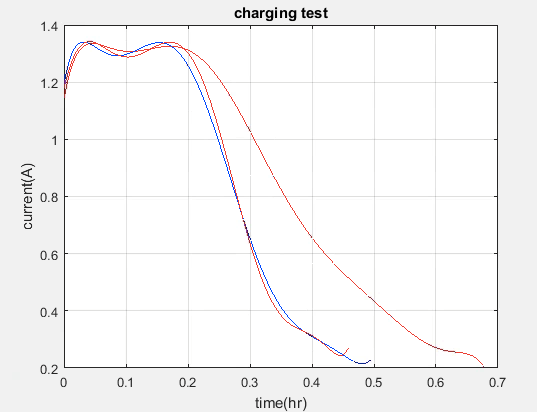
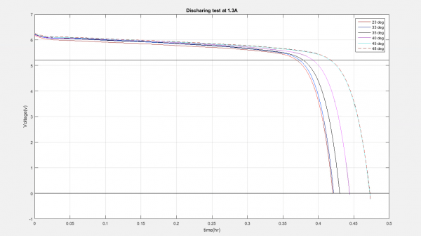
Various results obtained using the battery test system, by implementing battery charging or discharging test at different temperatures.

Figure: Test results charging tests
Figure: obtained current in charging tests
Figure: obtained current in charging tests
Figure: Test results in discharging tests
Figure:
Figure:
Conclusion
The use of CBA IV in this project is very effective in order to measure the experimental data comprehensively by using a computer. The characteristics of battery are significantly influenced by its operating temperature especially battery capacity and it is proven in this project.
