Projects:2016s2-220 Path Planning and Collision Avoidance for Aduino Robots
General Information
Description: The purpose of this project is to design a robotic system for path planning in congestion area. Potential applications are in autopilot urban transportations. The robot will be located using vision measurement through a camera. The robot models are established as two-wheel discs. Virtual obstacle clusters are manually inserted into the image frame and the computer needs to calculate a suitable path to a user-defined destination. As the obstacles are considered to be physical, collision avoidance is required. The robot can be equipped with sensors and the computer captures images from the vision stream. The communication between the computer and the robots will be through WiFi. Matlab, c++, OpenGL, and OpenCV are some of the softwares, languages and libraries to choose from.
Group number:220
Students: Michael Vieceli; Yuanyang Wang; Di Zhang
Superviosrs: Professor Peng Shi & Professor Cheng-Chew Lim;
Technical advisors: Dr. Hongjun Yu & Dr. Bing Yan
Contents
1.Introduction
1.1 Motivation and background
Image processing techniques are widely used in industrial automation for quality control, condition monitoring and increasingly for motion control. Image processing provides absolute state feedback which can be combined with conventional position sensors to reduce the impact of accumulative error through the course of repeated movement. Although uncertainty introduced into the imaging system through noise, perspective compensation and increased computational delay, these uncertainties tend to be constant over time. Overhead cameras also provide the benefit of analysing an environment for obstacles, personnel and other locomotive bodies which would interfere with the unobstructed movement of a robot or vehicle. The goal of this project is to identify obstacles and a robot in a given area, calculate a safe path and then traverse the path. Positional feedback will also be used to improve the resulting motion of the robot. The environment analysis is to be conducted in real-time.
1.2 Objectives
(a)Design a software system for path planning to calculate and execute traversal to destination, while adopting an efficient path and avoiding collisions with obstacles.
(b)Design a hardware system, including a camera, computers, and a Quanser robot, to perform the task.
1.3 Project Structure
The entire project is divided into three major parts:
1.Environment Analysis
2.Path Planning
3.Motion Control
and the design of a graphical user interface (GUI) as the project team has three members. Michael Vieceli is responsible for the environment analysis, Yuanyang Wang focuses on path planning, and motion control is assigned to Di Zhang. A GUI is designed to integrate individual’s work for hardware implementation.
2.System Overview
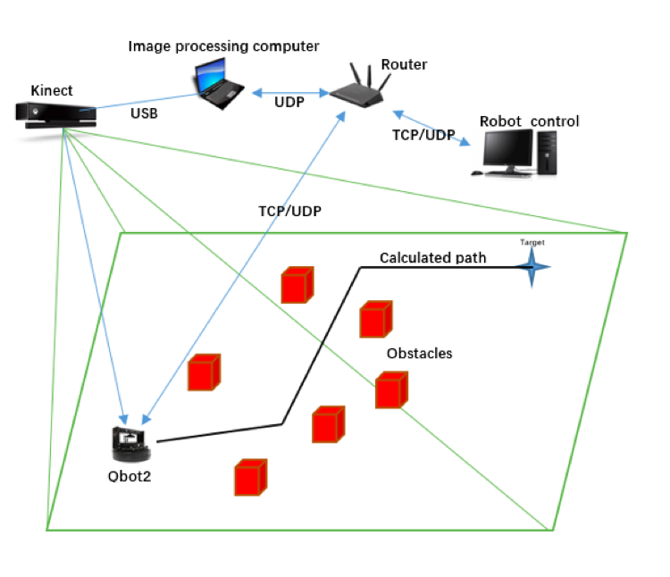
The figure below shows the integration of the whole system with input and output labeled.
2.1Hardware
• Microsoft Kinect V2 Camera
• Quanser Qbot2 robot
2.2 Software
• The Image Processing software locates objects and provides robot location and bearing.
• The Path Planning software and GUI adds virtual obstacles and calculates the optimal path
• The Motion Control Simulink Model calculates control parameters based on calculated path, robot location and orientation.
3.Image Processing
3.1 Methods
1. Image Capture
2. Down-sample
3. Projective Transformation
4. Thresholding and Segmentation
5. Feature Extraction
6. Classification of Objects
7. Describe Environment for path planning
8. Provide positional feedback for control system compensation
3.2 Results
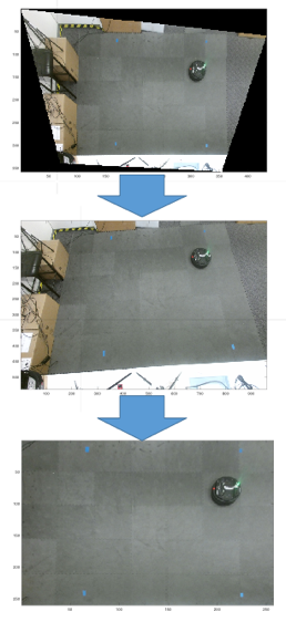
An example output of the projective transformation is shown below. This stage allows the image to represent a two-dimension Cartesian plane which aids in geometric calculation accuracy
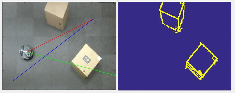
Example outputs of the classification and feature extraction phases are shown below.
Left: An example of calculated motion parameters. Blue denotes the current path segment, Red indicates distance to destination and Green indicates the current robot bearing.
Right: The robot’s environment with only obstacles highlighted, after the robot is automatically removed from the frame.
4.Path Planning
4.1 Method
The intended method is based on A-star algorithm.
A-star algorithm is devised by P.E.Hart et al in 1968 [2] as an improved algorithm of the Dijkstra algorithm. It uses heuristic searching approach to calculate optimal path. The basic thought of this algorithm is to define a measurement standard, such as the length of path, then find out the waypoint with the least cost of all the possible waypoints. From this waypoint, waypoints tree is constructed and new waypoints with the least cost are addressed until the target is reached. The A-star algorithm is a heuristic search algorithm and works well in simplified environment.
A-star algorithm:
𝑓(𝑛) = 𝑔(𝑛) + ℎ(𝑛)
The optimal path search algorithm is based on calculation of historic cost g(n) and heuristic cost h(n). The optimal path nodes are found by minimizing the total cost function f(n).
4.2 Results
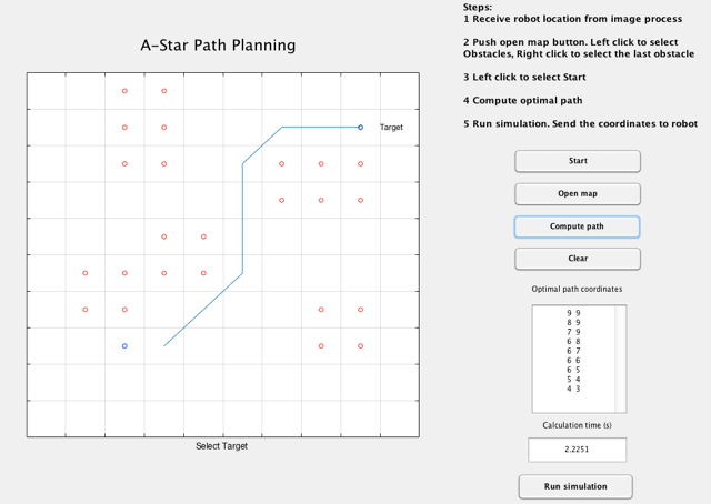
Example of path calculated in the GUI using virtually added obstacles:
5.Motion Control
5.1 Kinematic Model
Differential drive often used in two-wheel drive system which each wheel is equipped with a separate actuator. The Quanser QBot 2 Mobile Platform uses it, two separately coaxial driven wheels placed on either side of the robot body which controlled by high-performance DC motors with encoders and drops sensors.
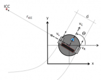
In the figure represent the radius of the wheels, the rotational speed of left and right wheel are wl and wr respectively. Thus, the equations of the linear speed of the left wheel and right wheel are vl=wl*r and vr=wr*r.
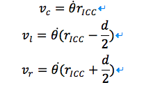
If only one of the two wheels rotates, the robot will rotate about the non-moving wheel. If two wheels rotate with the same speed, the robot will rotate one point which is far from the robot. The center of this point is Instantaneous Centre of Curvature (ICC). The distance from the center of the robot to the ICC is r(icc) and the distance between two wheels is d, θ is the angle of the robot, and the robot speed is vc. Then the equations of QBot 2 are:
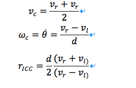
Given the wheels speed are vl and vr , the robot speed is which all along the same axis. Then the following express the kinematic model for the different drive system:
5.2 Trajectory tracking results
Control is the basement of navigation and path-planning of the robot, thus the higher requirement of stability, robustness, and accuracy are needed. As a further step of development to ensure correct operation of the robot, PID control using motion parameters and upcoming path steps to ensure ideal operation of the robot, with minimal overshoot and error inherent in the previous stages of motion design. To achieve desired controlling effect, the fuzzy PID method was employed to control the motions of tracking robot.
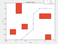
In the picture shows the simulation result of trajectory control.
6.Conclusion
The outcome of the final system demonstrates that the aims of the project are successfully reached. The image processing system is capable of identifying obstacles and robot and is able to monitoring the robot navigation while sending correction information to the robot. The path planning system based on A-star algorithm calculates and delivers optimal path efficiently with the given map information. The Quanser robot control system uses Simulink model to control the robot to navigate following calculated path to a satisfied level. Overall, the three main parts of the whole system cooperate well to perform a collision-free robot navigation in an environment with static obstacles.
7.Reference
[1] N Wang and P Chen, ‘Path planning algorithm of level set based on grid modeling’, in: Computer Design and Applications (ICCDA), International Conference, June 25-27, 2010.
[2] P. E. Hart et al., ‘A formal basis for the heuristic determination of minimum cost paths’, In: IEEE Transactions of Systems Science and Cybernetics, vol. ssc-4, no.2, July, 1968.
