Projects:2016s2-230 New Materials for Wearable Antennas in Flexible Electronics
Contents
Supervisors
Prof Christophe Fumeaux, Shengjian Chen
Group Members
Maria Philip, Yao Xu
Introduction
Motivation
Wearable electronics have become the latest trend and the next big thing in electronics. Wearable electronics require antennas which are lightweight, compact and flexible. However, the conventional materials used to realize antennas make them heavy, rigid, bulky and uncomfortable to wear. A conventional antenna’s performance is greatly affected by mechanical strain (bending and twisting) and may lead to breakage or variation in performance. Conventional antennas may also fail to function properly when subjected to mechanical strain. Thus, this arises the need for new materials which can make the antennas lightweight, compact, flexible and able to withstand mechanical strain without much variation in performance.
Background
Emerging wearable communications systems will increasingly require flexible antennas, in particular antennas which can be integrated into clothing and are able to adapt their shape to various movement of the body. This will allow exploiting the area of clothing to create efficient antennas in critical applications such as communications and tracking for defense or safety personnel, or monitoring of patients in a hospital. The next generation of flexible electronics require antennas that are light-weight, compact, flexible and low profile. To conform to these specifications new materials are being identified and used to make flexible antennas. New substrate materials include Fleece, Felt, PF4 (foam) and Polydimethylsiloxane (PDMS).The New conducting media include Liquid metal Alloys (EGaIn), Silver Nanowires (AgNWs), E-fibres, conductive polymer, Silver fabric and Graphene [1]-[8].

Aim
The objective of the project is to identify alternative materials for making flexible antennas as well as designing, fabricating, measuring the performances, and comparing the performance of the new antennas.
Antenna Design and Simulation
In order to overcome the inflexibility problem of conventional antennas, two types of antennas are designed using flexible materials, namely resonant and non-resonant antennas. In this project, two microstrip patch antennas at resonant frequency of 5.8 GHz and two UWB antennas were designed using PF4 foam as the substrate material and silver fabric and copper foil as the conductive materials.
Material Selection
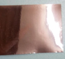
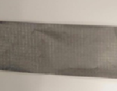
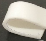
Copper foil and silver fabric were used as conducting materials, their sheet resistances is less than 0.0005 Ω/sq and 0.01 Ω/sq [7][8]. PF-4 was used as substrate material with dielectric constant of 1.06, loss tangent of 0.0001, thickness of 1.6 mm [5].
| Copper foil | Silver fabric | PF-4 |
|---|---|---|
 |
 |
|
Microstrip Patch Antenna Desgin
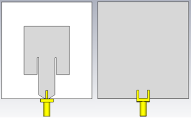
Microstrip patch antennas includes three basic elements. The bottom part is the ground plane using a conducting material. The middle part is a substrate using a dielectric material. The top part is a patch using a conducting material [9]. The same size of microstrip patch antennas using copper foil and silver fabric as conducting materials respectively and FR-4 as the substrate material were designed to work at 5.8 GHz in CST as shown in the figure below.
Ultra-wideband Antenna Desgin
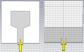
The structure of a UWB antenna with a truncated ground plane has a structure similar to a microstrip patch antenna; the only difference is that the ground plane does not extend over the entire surface of the substrate [6]. In a coplanar UWB antenna the ground plane and the patch are aligned on the same surface of the substrate. The same size of UWB antennas using copper foil and silver fabric as conducting materials respectively were designed in CST, as shown in the figure below.
Simulation
- Reflection Coefficient (|S11|)
The │S11│ plot of the antenna prototypes are plotted below. The │S11│ plot of antenna is used to determine the functional bandwidth of the antenna. The bandwidth of the antenna is the range of frequencies for which the reflection coefficient is less than -10dB. A -10dB reflection coefficient indicates that 30% of the received power is reflected. A │S11│greater than -10dB indicates that more than 30% is reflected. This is not advisable for the proper functioning of an antenna.
- Radiation Pattern
The radiation pattern of antenna is defined as the variation of the power radiated by an antenna as a function of the direction away from the antenna [9]. 2D radiation patterns, which are orthogonal cross sections of the 3D radiation pattern, are often analyzed in applications.
Fabrication of Antennas
Fabrication of Silver Fabric Antennas
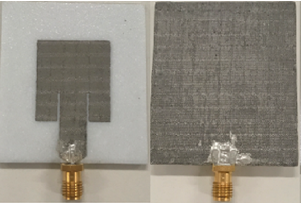
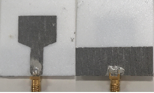
The textile antenna is made from silver fabric and PF4.The silver fabric is attached to the PF4 substrate using fabric glue. In order to fabricate the silver fabric antenna, the silver fabric is cut using Protolaser machine. Due to the presence of plastic in the fabric, the fabric does not detach completely. The PF4 substrate is cut to a size larger than the size of the antenna. Then 4 holes are made on it so that it can be placed on the 4 leg Jig. The holes are made on the silver fabric. Fabric glue is applied on the PF4 substrate and the silver fabric is placed on the topside of the PF4 substrate. Once the fabric glue dries the unwanted silver fabric is teased out using a scalpel. Then, it is removed and turned and the back side of the antenna is fabricated in a similar manner. Once the glue dries, the antenna is cut to obtain the silver fabric antennas of the required dimension. The SMA connector is attached to the antenna using conductive epoxy. The front and back view of the fabricated silver fabric antennas in the figure below.
Fabrication of Copper Foil Antennas
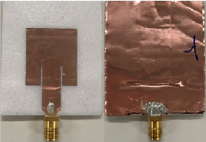
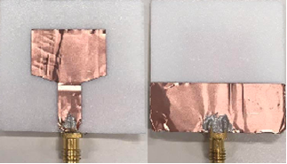
The antennas are made from copper foil and PF4 substrate. The fabrication of copper foil antennas are similar to the fabrication of the silver fabric antennas. The copper foil has adhesive hence does not require another adhesive agent. The copper foil makes a cleaner cut under the laser. Hence, does not require teasing. The SMA connector is attached to the antenna using conductive epoxy. The front and back view of the fabricated copper foil antennas are shown in the figure below.
Antenna Measurement
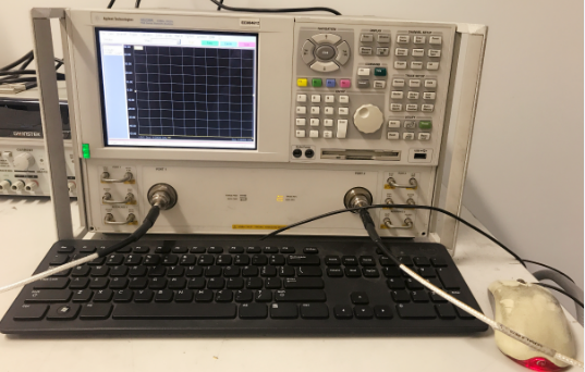
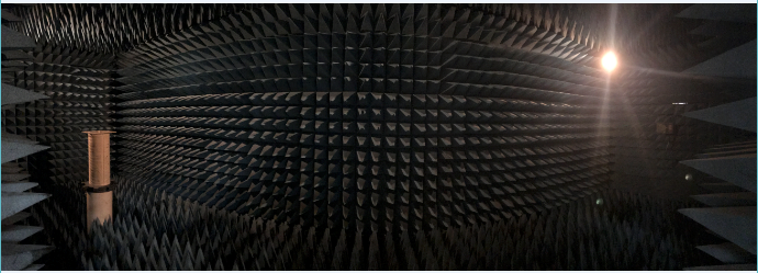
The antenna prototypes performance was measured using a vector network analyzer (VNA), an anechoic chamber, standard gain horn antennas, cables, tools and a computer with MCM-20turntable controller software. The anechoic chamber consists of a transmitting antenna, turn-table and foam spikes which prevent sound and electromagnetic radiation from travelling through the walls of the chamber.
Reflection Coefficient
|S11| was measured by the VNA. The VNA was first manually calibrated employing the ACP 3.5 female connectors of the 3.5mm Economy Calibration Kit. Then, the antenna prototypes were connected to the VNA. The obtained result was saved as “.s2p” file.
Radiation Pattern
The radiation pattern of the antenna prototypes were obtained by measuring the antenna performance in an anechoic chamber on a turntable. The UWB antenna prototypes performance were measured in XY,XZ and YZ planes in the frequency range between 1 GHz to 20 GHz turning the antenna from -180 degree to 180 degree. The microstrip patch antenna prototypes performance were measured in XZ and YZ planes in the frequency range between 4 GHz to 8 GHz turning the antenna from -180 degree to 180 degree. The co-polarization and cross- polarization measurements of the antenna were obtained by turning the transmitting antenna in each plane. The Standard Gain Horn Antennas (SHA) 639, 640, 642,643 and 644 were measured in the anechoic chamber on turntable and turning it from -10 degree to 10 degree.
Results
Microstrip Patch Antennas
- │S11│
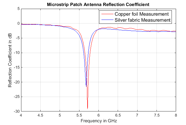
Matlab plots out the measured |S11| of the two microstrip patch antennas as shown in figure below. The lowest value of the antenna using copper foil is -29.2 dB at 5.72 GHz. The lowest value of the antenna using silver fabric is -21.5 dB at 5.68 GHz.
- Realized Gains
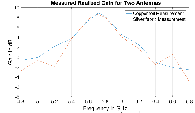
The highest realized values of measured realized gains are 8.5 dB and 8.0 dB for using copper foil and silver fabric respectively. The measured realized gains for using copper foil and silver fabric are 7.7 dB and 7.5 dB at 5.8 GHz.
- Radiation Patterns
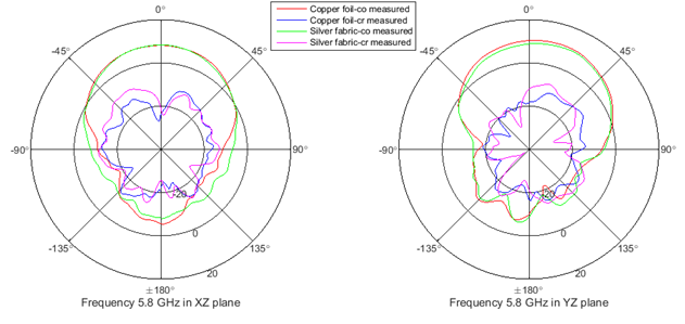
In the XZ plane, the biggest co-polarization gains are 8.3 dB and 8.5 dB for antennas using copper foil and silver fabric, and the same substrate material PF-4. In the YZ plane, the highest co-polarization gains are 10.2 dB and 9.8 dB using copper foil and silver fabric respectively. Thus, the performances of the two microstrip patch antennas are effective at 5.8 GHz, which meets the design requirements.
UWA Antennas
- │S11│
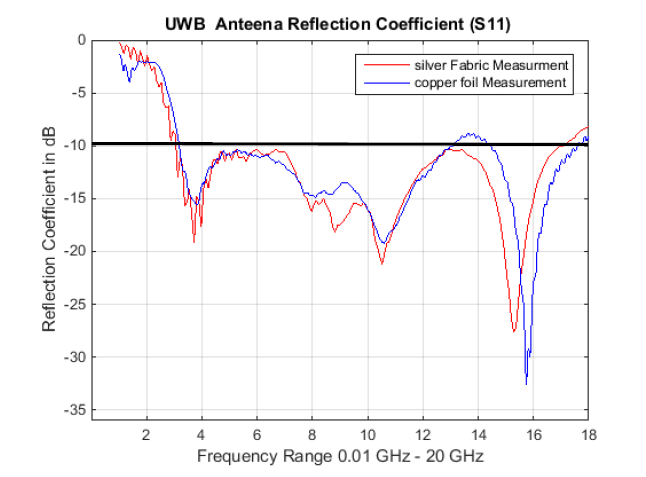
The measured reflection coefficient of copper foil and Silver fabric antenna prototypes are shown below.
From the figure it is observed that the │S11│ plot and range of operating frequencies of the silver fabric antenna is better than that of the copper foil.
- Realized Gains
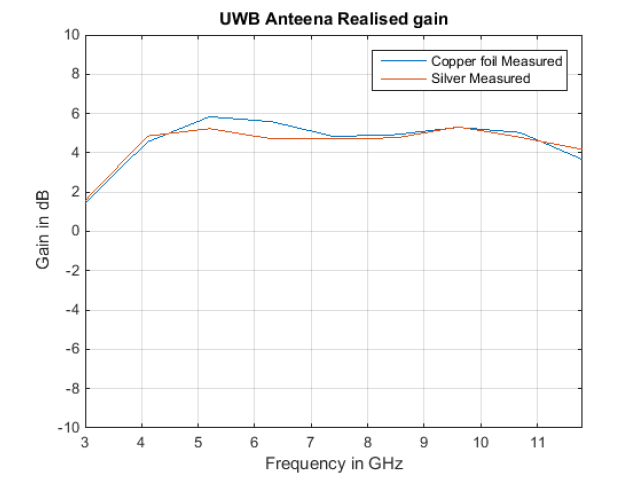
The copper foil antenna has higher realised gain between frequencies 4.5 GHz and 7.5 GHz. The realised gain of the silver fabric antenna is very similar to that of the copper foil antenna for the remaining frequencies.
- Radiation Patterns
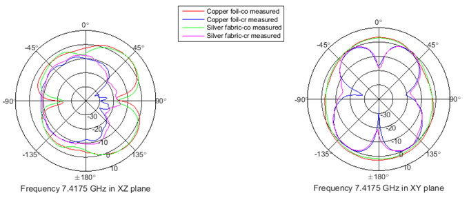
The measured radiation patterns of copper foil and Silver fabric antenna prototypes in XY and XY planes are shown below.
Conclution
The conventional materials used to realize antennas make them heavy, rigid, bulky and uncomfortable to wear. Moreover, a conventional antenna’s performance is greatly affected by mechanical strain (bending and twisting) and may lead to breakage or variation in performance. The new materials that are suitable for fabricating wearable antennas in flexible electronics. A copper foil antenna was fabricated in the same dimensions as the silver fabric antenna. It was observed that the silver fabric flexible antenna had performance similar to that of the copper foil. Silver fabric has better tolerance to bending. Hence, it is more suitable for wearable antennas.
References
[1]Hayes, GJ, So, JH, Qusba, A, Dickey, MD & Lazzi,G, 2012, ‘Flexible liquid metal alloy (EGaIn) microstrip patch antenna’, IEEE Transactions on Antennas and Propagation, Vol.60, pp. 2151-2156.
[2]Wang, ZY, Zhang, LL, Bayram, Y & Volakis, JL 2012, ‘Embroidered conductive fibres on polymer composite for conformal antennas’, IEEE Transactions On Antennas And Propagation, Vol. 60, pp. 4141-4147.
[3]Salvado R, Loss C, Gonçalves R & Pinho, P 2012, ‘ The use of Textile materials for the design of wearable antennas: a survey’, Sensors (Basel, Switzerland), Vol. 12, pp.15841-15857.
[4]Song, L, Myers, AC, Adams JJ & Zhu,Y 2014, ‘Stretchable and reversibly deformable radio frequency antennas based on silver nanowires’, Acs Applied Materials & Interfaces, Vol. 6, pp. 4248-4253.
[5]Cuming Microwave 2011, C-FOAM PF-2 and PF-4, Technical Bulletin, viewed 13 August 2016,
<https://www.cumingmicrowave.com/pdf/210-Dielectrics/210-6%20C-FOAM%20PF-2%20&%20PF-4.pdf>.
[6]Lin, Y, Hung, K, ‘Compact ultrawideband Rectangular Aperture Antenna and Band-Notched Designs’, IEEE Transactions On Antennas And Propagation, Vol. 54, pp. 3075-3081.
[7]The EMF Safety Shop, High Quality Silver for Performance, Shielding & Conductive Fabrics, viewed 2 May 2017,
<https://www.lessemf.com/1220.pdf>.
[8]Parker Seals, CHO-FOIL EMI Shielding Tape with Conductive Adhesive (Copper, Aluminum or Tinned Copper), Laminates & Grounding Products, viewed 2 May 2017
[9]Balanis, CA, 2005, Antenna Theory, Analysis and Design, 3th edn, Wiley Inter Science, New York.
