Projects:2017s1-182 BMW Autonomous Vehicle Project Development of Vehicle Control Algorithm
The Development Vehicle Control Algorithm project is a component of the Autonomous Vehicle Development Project
Investigation of numerous control strategies to determine the ideal steering angle to enable an autonomous vehicle to follow a predetermined path whilst also providing a comfortable ride for all its occupants. Utilizing the core principles of feedback control systems, signal processing and complex domain vector calculus, the control strategy is capable of track manipulation, predictive pathing and past-movement compensation to ensure a a smooth and accurate ride is achieved.
To enable this control strategy development, a system model has been developed to simulate the real-world performance of a given control strategy. This system model represents the larger BMW system to allow easy integration of the chosen control strategy into the current autonomous development vehicle platform. This model allows the control strategy to be tested on a variety of different paths.
Contents
Motivation
This project is component of a larger project run by Robert Dollinger that aims to develop the systems required to operate an autonomous BMW. Some autonomous modules have been previously completed; however there are still a portion of systems that have not been developed or only been partially developed
Objectives
1. Create a variety of algorithms that use minimal steering wheel angle to remain on a predefined track with minimum deviation.
2. Develop a simulator in which vehicle control algorithms can be tested
3. Test algorithms on the simulator and fine tune VCA’s
4. Evaluate which of vehicle control algorithms tested would serve as the best foundation for future development
Vehicle Control Algorithm
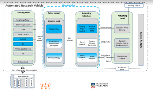
The vehicle Control Algorithm is a module of Autonomous vehicles within the driver strategy portion of an autonomous system, this module is responsible for providing the steering wheel angle required to keep the vehicle on the desired track, this module then sends that information to the actuating interface so that it can interact with the vehicle.
Developed System
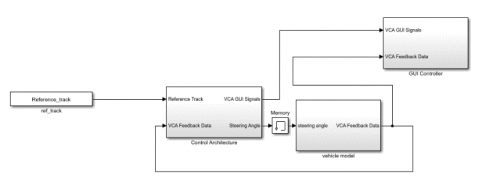
Our approach to the algorithm splits it into three major sub-modules; the Control Module, the Vehicle Model and the Export/GUI module. each of these module is designed to be separate from one another to allow for them to be independently developed and inserted into the final product.
The program is designed to take in a reference track provided by the vehicle model
One of the major features of our VCA is that it does not project the required steering angle ahead it instead calculates the change of each point along the track with a deviation from the track used as a control mechanism.
GUI/Export Module
This module is designed to take in vehicle information for each cycle and store that data accordingly, once the system has run through the course this information is visually displayed to the user allowing for determinations on the efficiency of the system
Vehicle Model
The purpose of the vehicle model is to take the characteristics of the vehicle in motion to project the future behavior of the vehicle as it progresses on the track. This information takes the current coordinates of the vehicle along with the velocity and steering angle and projects the future coordinates the vehicle is expected to be at, this information flows through to the position control module to allow for adjustment of the steering angle.
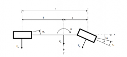
The vehicle model architecture is based on the usage of the bicycle model, this sub-system takes in velocity and steering angle and determines an expected velocity, using the provided velocity it then calculates a predicted position east and north. This information is instrumental in controlling the vehicle as it provides the necessary information to accurately track the movement of the vehicle. This module fits into both the control module as well as the GUI with an input of steering angle from the feedback of the steering rack.
The module of three major sub-modules:
1. Variable initialisation
2. Determination of travel
3. Determination of position.
Bicycle Model
Initilization of Variables
The purpose of the initialization program is to handle all inputs within the system and assign them to be used in the later modules, these variables are either feed in through the Simulink input into the system or through the MATLAB workspace.
Determination of Travel
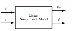
The purpose of the determination of travel module is to take in the variables previously initialized and run a linear single-track model so that the variables required to determine direction can be determined. Due to the longitudinal forces on the vehicle it does not travel at the same angle as steering angle, the follow module allows for the extraction of the two variables that can give the true angle of the vehicles travel.
The system runs this model through a state based formula that takes in the general characteristics of the vehicle and outputs the expected behaviour of the vehicle As can be seen in this equation the new state of Yaw rate and Side Slip both rely on the numbers of their previous states. Due to this requirements feedback is built into the system to return the output of this equation into the next iteration.
ψ(PSI_estimated)=ψ_initial+(ψ ̈(yaw acceleration)+ψ ̇(yaw rate))*time
Direction of travel=PSI_estimated-β
Determination of Position
The Determination of Position is designed to generate the expected position based on the information generated within both of the previous modules. This system takes in a velocity vector that is run alongside the initial position of the vehicle to output the estimated position of the vehicle after the cycle time.
Vehicle Control Module
The goal of the vehicle control module development project was to develop a control strategy to determine the ideal steering strategy to enable a car to navigate around a predefined track smoothly and accurately.
The developed strategy was a significant improvement on the existing strategy. Especially when tuned for a specific speed. A tool for tuning the car for a specific speed was also developed. The strategy involved the following sub systems:
• Determining the position of the track from the car and turning the car towards the track. More aggressive turning is used when the car is further from the track.
• The rate at which the car approaches the track is considered to prevent overshoot.
• Predictions are made comparing the future position of the car from the next segment of track to anticipate turns and reduce overshoot.
• Steering controls are smoothed through use of filtering and averaging.
Path Filtering
When segments of the track approach or intersect other segments of the track, it may cause confusion as the deviation could be calculated from this alternative path. The solution to this issue is to filter the track such that only a short linear path is used deviation calculation. A small sample reference points are selected based on the segment starting location and the segment distance.
The segment starting location for the first segment is the first point in the reference track. The segment starting location is then incremented forward through the track as the car progresses around the track. This incrementation forces the car to progress through the track in the intended direction of travel as the targeted path will never be behind the current path segment.
Deviation Calculation
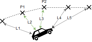
To determine the position of the path from the car, the distance from each pair of points to the car is calculated. The pair of points that are closest to the car will be used to calculate the car's distance from the track. These points are P1 and P2.
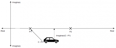
To determine the shortest distance from the car to the line segment that joins the two chosen points, a spatial transform is used so that the car and points can be represented in a space where the points P1 and P2 like on the real axis.
After this transformation is applied, the deviation from the track can be calculated by taking the imaginary component of the car's vector position. Point P1 is used to calculate the car's vector position and the basis of future path filtering.
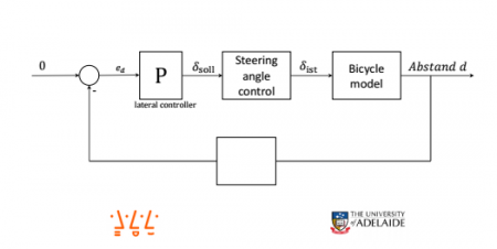
Proportional Integral Derivative Controller
The control system used to control the steering angle
Output Filter
Due to limitation in the real world equipment the change of steering angle over time must be limited by the software to provide and accurate result within the system. To achieve this a limiter has been added to the simulink module
Results
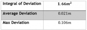
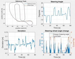
The results of the system show an average deviation from the track of 2cm with a maximum deviation from the path of 10cm
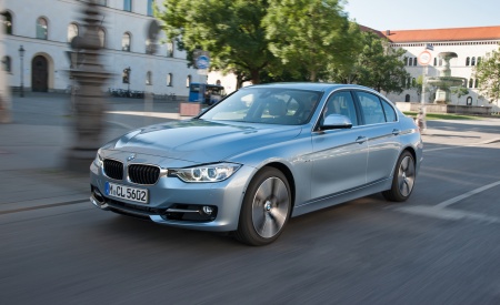
The vehicle platform that this system is designed for is a 2013 BMW ActiveHybrid 3 with a width of 1.81m assuming a lane of 3.4m this leaves +/- 79 cm of lane on either side With a maximum deviation of +/-10cm our vehicle is well within the limits of the lane and if it stays within this state should safely traverse the track set out for it. The steering wheel angle shows relatively limited jitter which means that the passenger should experience a reasonably smooth ride.
Project Team
Harrison Gruber
Undergraduate Electrical and Electronics Engineer(Honours)
Born in Sydney, Australia Harrison is a final year Electrical & Electronics Engineering student at the University of Adelaide, he has worked within the industry both as a Software engineer for QinetiQ Australia and a Quality Engineer for Holden Australia, Once completing his degree he plans to enter the automotive field as a Product Development Engineer.
Throughout the development of the Vehicle Control Algorithm Harrison has been responsible for Control System Research, development of the GUI and development of the Vehicle Model.
Peter Branson
Undergraduate Electrical and Electronics Engineer(Honours)
Peter is a student at the University of Adelaide studying his final year of Electrical & Electronics Engineering. He has a keen interest in digital, computer and control systems especially in the fields of electronic-autmotive industries and biomedical instrumentation.
Peter completed his internship developing computer systems to automate office tasks and enable better site-wide communications for the GM Holden supply team. He is currently seeking graduate employment for when he completes his studies in Novemeber 2017.
Responsible for Control System Research and Control Module Development.
www.linkedin.com/in/peter-branson-a2b770109
Peter.Branson@student.adelaide.edu.au
Supervisors
Nesimi Ertugrul
Associate Professor Adelaide University
Robert Dollinger
Dr Wen Soong
Wen L. Soong was born in Kuala Lumpur, Malaysia. He received the B.Eng. degree from the University of Adelaide, Australia, in 1989, and the Ph.D. degree from the University of Glasgow, U.K., in 1993. For four years, he was engaged as an Electrical Engineer in the Power Controls Program, General Electric Corporate Research and Development, Schenectady, New York, before joining the Electrical and Electronic Engineering Department, University of Adelaide, where he is currently an Associate Professor. His research interests include permanent magnet and reluctance machines, renewable energy generation, and condition monitoring and diagnostics.
References
[1] Alleyne, Andrew. 1997. “A Comparison of Alternative Intervention Strategies for Unintended Roadway Departure (URD) Control.” Vehicle System Dynamics 27 157-186.
[2] B.J. Alshaer, T.T. Darabseh, M.A. Alhanouti. 2013. “Path Planning Modelling And Simulation Of An Autonomous Articulated Heavy Construction Machine Performing A Loading Cycle.” Applied mathematical Modelling 37 5315-5325.
[3] Bardini, Dieter Schramm Manfred Hiller Roberto. 2014. Vehicle Dynamics Modeling and Simulation. Springer.
[4] Dollinger, Robert. n.d. “BMW Autonomous Vehicle Project.”
[5] E. Kim, J.Kim M, Sunwoo. 2014. “Model Predictive Control Strategy For Smooth Path Tracking Of Autonomous Vehicle With Steering Actuator Dynamics.” International Journal of Automotive Technology Vol 15 No 7 1155-1164.
[6] F. Borrelli*, P. Falcone, T. Keviczky. n.d. “MPC-Based Approach to Active Steering for Autonomous Vehicle Systems.”
[7] Guilherme V. Raffo, Guilherme K. Gomes, Julio E. Normey-Rico. 2009. “A Predictive Controller for Autonomous Vehicle Path Tracking.” IEEE TRANSACTIONS ON INTELLIGENT TRANSPORTATION SYSTEMS, VOL. 10, NO. 1 92-102.
[8] Hawes, Dr Nick. 2016. “Driving the revolution.” University of Birmingham.
[9] Jesse Levinson, Jake Askeland, Jan Becker. n.d. “Towards Fully Autonomous Driving: Systems and Algorithms.”
[10] 2015. Controlling Self Driving Cars. Directed by AerospaceControlsLab. Performed by Shih-Yuan Liu,Brett Lopez, Luke Johnson Justin Miller.
[11] K.J Astrom, T Hagglund. 2001. “The future of PID control.” Control Engineering Practice 9 1163–1175.
[12] Martin Buehler, Karl Iagnemma. n.d. “The DARPA Urban Challenge Autonomous Vehicle in City Traffic.” 249-251.
[13] Ramanata, PP. 1998. Vehicle Dynamics Modeling.
[14] Riccardo Marino, Stefano Scalzi, Mariana Netto. 2011. “Nested PID steering control for lane keeping in autonomous vehicles.” Control Engineering practice 19 1459-1467.
[15] S. SAHOO, S. C. SUBRAMANIAN, N. MAHALE and S. SRIVASTAVA. 2015. “Design And Development Of A Heading Angle Controller For An Unmanned Ground Vehicle.” International Journal of Automotive Technology Vol. 16 No. 1 27−37.
[16] https://www.caranddriver.com/reviews/2013-bmw-activehybrid-3-first-drive-review
