Projects:2018s1-196 Concealed Wearable Antennas
The aim of this project is to design two button antennas as wearable technology that can be attached to the clothes. The button will be designed based on metallic antenna plates and another one based on dielectric plates. The simulation tools of Computer Simulation Technology, CST will be used for simulation and the designs will be fabricated and tested in real life. The antennas also should be designed with 2.4 GHz and 5.8 GHz frequency band and have Omni-directional radiation patterns.
Contents
Introduction
The wearable technology become important to our daily lives in this new development era. So, button antenna is chosen as the best candidate for wearable antenna. As we know, buttons are already included in many clothes that we wear every day. They can be located in different areas on textiles as well such as on t-shirt, jeans, jackets and others. Some of them also using multiple buttons on a cloth. So buttons are already heavily used in textiles or clothing. Users already accepted the look of the button so there is no need for users to refine the fashion or accept the new concepts as they already comfortable wearing buttons on their daily life. Many of them also already made from metal so incorporating metallic button in the antenna would not be a new concept to the users. The buttons also have small and circular in shape as well in which they are compact and easy to carry. Hence, there is an opportunity for buttons to serve a double-purpose which is ideal when looking at the wearable technology.
Project team
Project students
- Christian Colombo
- Siti Nurfatinah Faizal
Supervisors
- Prof. Christophe Fumeaux
- Dr. Shengjian Chen (Jammy)
Project status
Design, fabrication and testing completed.
Design Process
Design A: Siti Faizal
Design Overview
The first design is formed from a metallic, top-loaded monopole antenna, comprised of two metal discs separated by a low permittivity dielectric material. The antenna is fed by a microstrip line, which minimises the height of the assembly, and allows for it to be more easily incorporated into clothing. There is also a center pin in the middle of the antenna which connect the top plate with the ground plane in order to increase the strength of the button.The antenna then is mounted on a PF-4 Foam substrate with a conductive fabric ground plane.
Simulation Results
Figure 2 shows the performance of the antenna in terms of return loss (dB) vs the frequency (GHz). It has a desirable return loss of -30.65 dB at the low frequency of 2.45 GHz and -12.114 dB at high frequency of 5.8 GHz. As the reflection coefficient is lower at low frequency compared to high frequency band, so it is optimized for lower frequency operation. The major factor of getting the accurate matching frequency at both bands is by varying the diameter of the discs, cylinder and height of the antenna.
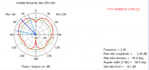
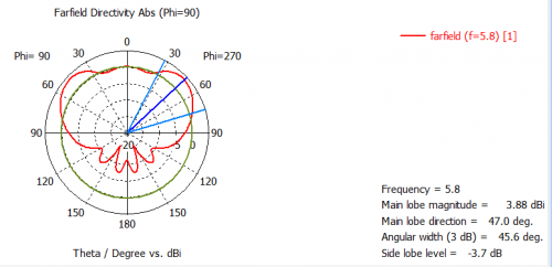
The radiation patterns of the antenna are shown in Figure 3 and 4. At low frequency band (2.4 GHz), the antenna has an Omni-directional pattern with gain 3.44 dBi. It has a doughnut shape pattern where the antenna is highly radiated around the antenna. Meanwhile for high frequency band (5.8 GHz), it has a directive pattern in which the antenna is highly directional and a lot of powers is been pointed towards upper direction. It has 3.88 dBi gain which is higher than the low frequency gain. The radiation patterns for both frequency seem to have a good pattern and being directed correctly as predicted.
Fabrication
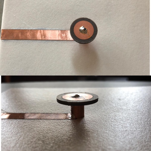
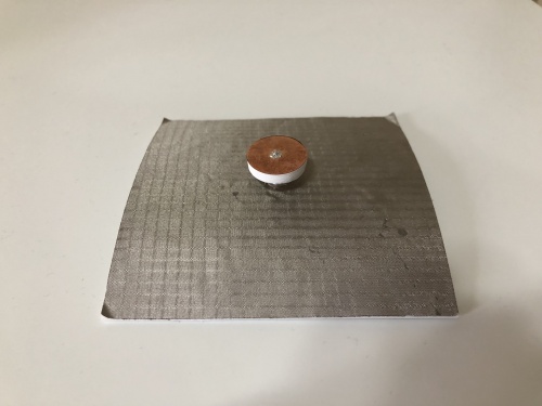
To do the fabrication, the dimensions of design antenna need to match with the materials that are planned to use. As for the top disc, RT/duroid 5880 is chosen. It is a laminate that consist of two copper plates at upper and bottom part and is filled with a dielectric with low permittivity of 2.2. It is a glass microfibre reinforced PTFE composites and is easily to cut which is suitable for the wearable button antenna.The cylinder part is made of a coaxial cable (RG401/U). The cable has three layers of material. The inner conductor which is the centre pin is made of copper rod, the dielectric type is a Teflon and the shield material is a copper tube. This cable can handle the frequency of 10 GHz and with impedance of 50 Ohms. The antenna is the mounted on a substrate with conductive fabric as a ground plane. A PF-4 Foam is used as the substrate as it is flexible to be put on clothes.
Testing
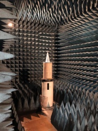
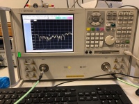
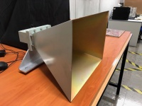
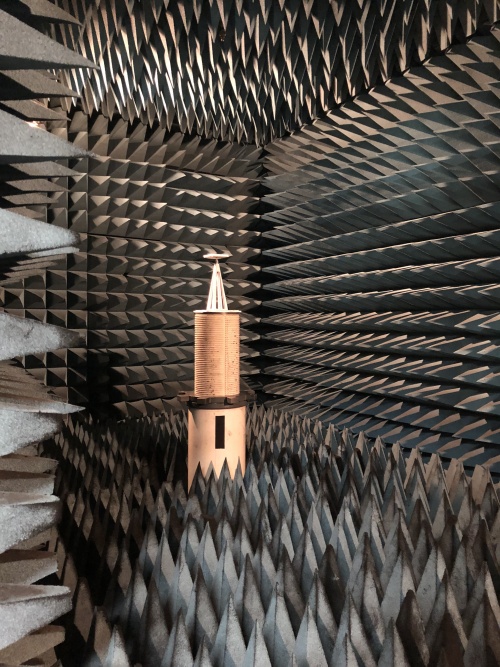
The testing process was done in an anechoic chamber in which the room is made of absorbing materials where it eliminates reflection and external noise caused by the electromagnetic waves. The antenna was tested for its performance of the return loss and radiation pattern. The return loss was measured by the Network Analyzer where it displayed the S-parameter result. The radiation pattern of the antenna was tested in the chamber. The antenna was placed on the positioning systems where it is rotating 360 degrees so the radiation pattern can be measured at all angles. Then, the transmitting antenna will transmit the signal to the receiving antenna and the data was sent to the PC to be recorded. Furthermore, the Standard Gain Horn Antenna also was measured. It is use for gain reference for antenna measurements. The measured gain at 2.4 GHz and 5.8 GHz was compared with the reference gain and find the difference between them.
Testing Results
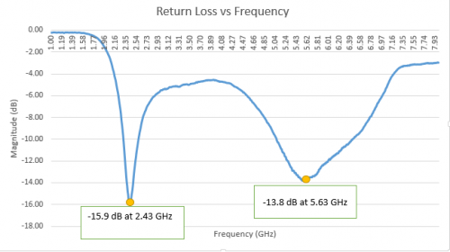
After testing the antenna, the results were recorded and plotted in excel. The S-parameter result shows the same curve as the simulation graph. There is only slightly difference for the matching frequency as it is reflected at 2.43 GHz and 5.63 GHz. The reflection coefficient increase a little bit compared to the simulation result but it still shows good matching with -15.9 dB at 2.43 GHz and -13.8 dB at 5.63 GHz. The radiation pattern also shows a good omni-directional pattern at both frequencies.
Design B: Christian Colombo
Design Overview
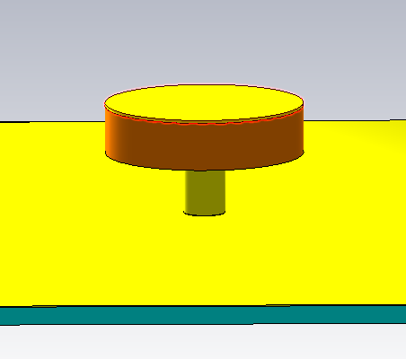
The design is based around a dielectrically loaded monopole antenna. The dielectric core forms the stem and top portion of the button, with a central pin that enters through the bottom of the dielectric stem, and terminates to a metallic disc at the top. This top disc allows for the antenna to achieve resonance at a relatively low frequency (2.4GHZ) while minimising the vertical height. The ground plane continues up the stem of the antenna, providing a grounding shield. This reinforces the structure, and allows for capacitive coupling with the interior probe, a characteristic which is critical in achieving the dual band performance. The antenna is fed by a coaxial connector below the ground plane, and the entire antenna assembly was modelled as mounted atop a sheet of velcro.
Simulation Results
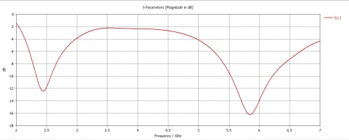
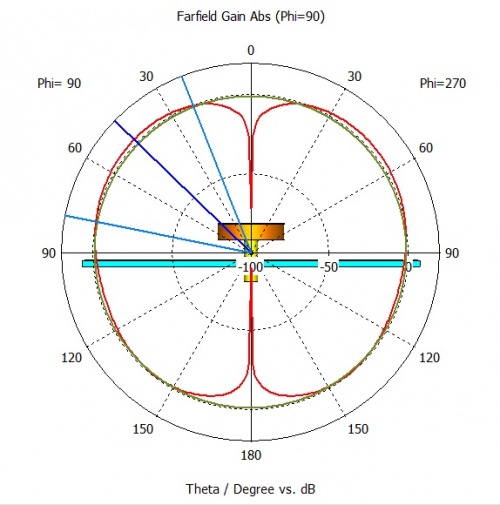
The results achieved through this design displayed optimisation in the second band rather than the first, achieving a reflection coefficient of around -12.4dB at 2.45GHz, and -16.2dB at 5.8GHz. The simulated radiation pattern, as desired, was largely omnidirectional. As expected from a monopole antenna, the low-band resonant frequency was largely determined by the height of the antenna, and radius of the top disc. The high-band resonant frequency was controlled by the height of the ground casing of the stem, as well as the radius of the stem. The impedance transition was carefully altered in an effort to match the performance at both bands.
Fabrication
During the design of the antenna, fabrication was envisioned to involve the use of a SMA connector, with the centre pin use as the main antenna probe through the structure (and hence any residual teflon removed). The dielectric material, carefully modelled with a permittivity of 8.2, was to be 3D printed using the ‘pre-fab’ material available for use within the university facilities. The impedance transition was intended to be a machined piece of metal, and the ground plane implemented as silver fabric.
However, as we approached fabrication, it became clear that the impedance transition, which was modelled as conical, would be too difficult to achieve, and the small gap modelled between the stem casing and the top of the dielectric structure too prone to variation. As a result, the antenna design was modified slightly to allow for more feasible cylindrical impedance transition, and no requirement for a gab in the ground casing.
While this did simplify the design and allow for more feasible fabrication, it was discovered that, due to the setting of the 3D printed material, some dimensions for the antenna were not realised as the same that were modelled. This proved difficult as, after many attempts, unfortunately we were not able to produce another model of the dielectric core due to difficulties with the 3D printer. Due to time constraints, fabrication needed to proceed using a dielectric core that was not to the ideal specifications.
Testing
Like with Design A, the antenna was tested firstly using a network analyser to determine the reflection coefficient performance in the frequency domain. Throughout this process, we learned how to properly calibrate the network analyser, and best practices for fastening connectors between cables and equipment. The anechoic chamber was used to test the radiation pattern in the both vertical and horizontal alignments, as well as in co-polar and cross-polarised antenna configurations.
Testing Results
The results demonstrated a reflection coefficient at 2.4GHz of around -12dB, which was in line with what was expected from simulation. However, the antenna did not exhibit the dual band properties as expected as the next resonant frequency was around 9GHz. It is unclear at this stage what could have caused this discrepancy, but as previously noted, there was difficulty in fabrication that led to a non-ideal construction, which may have influenced the results. The final step in the project is to try to replicate this result in simulation, and make a recommendation as to why the dual band did not perform as expected, whether it was due to construction, and how this could be rectified in future fabrications. The radiation pattern data gathered from the anechoic chamber is still under analysis, but a preliminary view demonstrates a largely omnidirectional radiation pattern as expected.
