Projects:2019s2-25102 Modelling of Magnetic Energy Conversion in the Periodic Domain
Abstract
Magnetic systems play a significant role in energy conversion as almost every type of energy conversion involves a magnetic device. For example, wind turbines and thermal energy use generators which is a magnetic device to produce electric energy by electromagnetic induction. A magnetic device such as generators, motors, and transformers have non-linear aspects that need to be considered. The non-linear aspects can be in a form of saturation, hysteresis, and eddy current.
Studying the effects of nonlinearities in an inductor choke circuit model will be the main motivation of this project. By conducting the experiment with the operating condition that can produce these nonlinear effects to be significant, detailed analysis will be performed to study the behaviour of the nonlinear effects. In order to get precise and accurate data from the experiments, more advanced tools need to be used such as PicoScope developed by Pico Technology.
Detailed analysis can be performed once all the data gathering process has been completed. By using a Fourier series method, the magnetic losses can be model out in a periodic domain which then can be studied further using statistical analysis.
Introduction
Modelling of Magnetic Energy Conversion in Periodic Domain is the calculation of unwanted behaviour that does exist when the energy was being converted to magnetic energy. From this project name, the magnetic energy was being converted in a periodic domain because of most of the result that this project get was not sinusoidal. Thus, it needs to be calculated in a periodic domain in which this project will use a Complex Fourier Analysis (CFA) and Inverse Complex Fourier Analysis (ICFA) in Matlab software to calculate the value of all parameters in the project model circuit. This project wanted to study the behaviour of each power loss that can exist during energy conversions like eddy current losses and hysteresis losses. The modelling will take place as the figure shown which the choke will be this project device under test.
Motivation
The modelling of magnetic energy conversion was important to many projects such as a project that involves magnetic energy conversion. The magnetic energy conversion was widely used in many areas like renewable energy, future energy, and even in autonomous systems nowadays. Besides, many applications involves with these losses like eddy current losses was currently being used as a braking system for most of the train. So, this project will be beneficial to all project that involves magnetic energy conversion. This was because one of the main objectives of this project was to study the power losses when magnetic energy conversion happens. The new knowledge that this project will bring to the people was how to examine the losses when doing an experiment involving magnetic energy conversion and how to reduce it to its smallest value. Besides, this project group needs to have new knowledge more on ferromagnetism, the effects of nonlinearities, and the separation of the power losses. Not to forget, this project needs to have new knowledge on how to handle the Gibbs effect, as this project will be using a Complex Fourier Analysis and Inverse Complex Fourier Analysis in a Matlab where the Gibbs effect is a natural phenomenon that exists when applying a Fourier Analysis.
Project team
Project students
- Mohamed Amin Bin Abdul Rafid
- Nabil Munir Bin Ahmad
- Nur Akhira Binti Kamar Baharin
Supervisors
- Dr. Andrew Allison
- Prof. Derek Abbott
Objectives
While the main aim of this project is to model a magnetic energy conversion in the periodic domain, the definite objectives of this project are:
- Study and understand the nonlinear effects in a magnetic devices.
- Modelling out the magnetic losses in the periodic domain (Fourier Method).
- Apply statistical analysis in measurement
- Simulation of magnetic properties.
Background
A magnetic device that is choke plays an important parameter that will be used in this experiment. This device helps with understanding nonlinear effects which will be testing by driving the device hard. It will be running with a high voltage up until its thermal limit. This choke consists of a series of inductors and resistors approximately at 2.28mH and 3.74 ohms, respectively. 240V transformer with 50Hz frequency is the main supply in this experiment. Some of the materials that will be used to be attached to the choke are iron and aluminium. However, before begins the experiment on iron and aluminium, the bare choke will be tested to get an air-core reading.
Data acquired through the experiment will be analyse in MATLAB software. Since this experiment handling thousands of data, it needs an efficient method to best examine them. Thus, Fourier Series is the method for modelling of the magnetic losses in a periodic domain. A code for the complex Fourier series is created and applied along with the obtained data code.
As soon as the data has been analysed, the result might produce quantization noise and propagation of error. Quantization noise is an unwanted signal that been bothering the ideal produced output. Propagation of error is the uncertainty in the result itself. It might come from random sources. Be it from the wire, the connection, or the technical devices from the experiment. These errors are unwanted errors that need to be removed and analysed. The solution for this issue is applying a statistical analysis that finding its mean value, variance, standard deviation, and many more.
The model will experiment with different types of core such as aluminium since aluminium produce high losses of eddy current which is our main objective of the experiment. The bare choke is being tested as it is linear and provides understandable behaviour. It is the base testing as a starting point to understand more on the model. Apart from aluminium, steel lamination will also be tested as it will produce all needed effects such as Gibbs effect, hysteresis loss, and eddy current loss.
Ferromagnetism
Understanding how Ferromagnetism works is key as it is the main mechanism that occurred throughout this project. In definition, Ferromagnetism is the magnetization processed that occurred to a ferromagnetic material such as iron in order to become a permanent magnet. This phenomenon can happen when a magnetic moment of the ferromagnet it means that the electron spins to be arranged in a regular manner [1].
The Curie temperature is defined by the temperature above the spontaneous magnetization that occurred vanished. When the temperature is below the Curie point, the electromagnetic moments of the ferromagnet lined up in a regular manner but it is possible that the magnetic moment is less than the saturation moment of the ferromagnet. Thus, an external magnetic field is required in order to saturate the material [1].
In relation to this research project, the operating condition of the ferromagnet tested involved a high voltage condition which will result in an increase in temperature to the magnetic device. It may affect the result gathered to a certain degree and can be analyzed further with a mathematical approach.
Losses in Ferromagnetic components
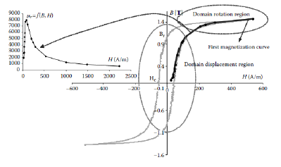
For ferromagnetic materials, the total iron losses can be both the hysteresis loss and the dynamic losses which include the eddy current loss and some excess losses. The hysteresis losses are most commonly related to the domain walls when the external magnetic field is applied to the ferromagnet [2].
Eddy current loss is the losses that occurred when the domain walls of the ferromagnet have some current being induced on it. The thickness of the core materials plays a part in this loss and the thickness of the material sheet can also affect the direction of the induced current [2]. Chen and Pillay in [3] mention that the changing external magnetic has a huge impact on the magnitude of the less depending on its rate.
Chua and Stromsmoe in [4] have discovered a mathematical approach to model the hysteresis loss in which the mathematical model is defined in equation (1).
𝑑𝑦/𝑑𝑡=𝑔𝑜[𝑥(𝑡)−𝑓(𝑦(𝑡))] [4] (1)
The equation above related the variable of x(t) and y(t) of a hysteresis loop. g() and f() in the equation are said to be increasing monotonically and are differentiable on to other functions that consist of nonzero slopes in the real line as long as it satisfies the property of g(0) = f(0) = 0 [5].
The Chua model parameters have been successfully interpreted physically by using a barlike domain wall model experimented in [5] which represents eddy current losses in soft magnetic materials.
Bertotti in [6] proposed a concept that is originally a concept of an elemental operator with a graphical interpretation and biaxial anisotropy which is called the Preisach model.
The excess losses are considered as the additional eddy currents that are being generated by the displacement of the domain walls of the ferromagnetic materials. These excess losses are affected by the time variation of the magnetic induction period.h
Method
Air-Core Design
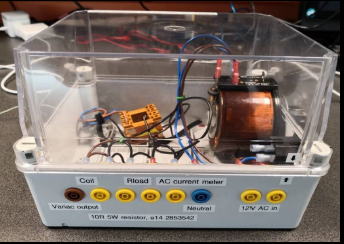
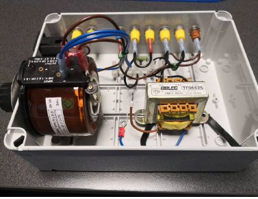
The figure above shows a definite model to be used throughout this experiment. Transformer, linear choke which consist of both resistor and inductor, two parallel resistors are the main device involve in the model. The connection is well arranged with a labelled section. Aluminium and electrical steel lamination are not yet to be tested. The first experiment is focusing more on-base choke which is an air-core device. The behavior of air-core needs to be analysed. Since the voltage will be driven hard, the current probably increasing, hence thermocouple is being attached to the choke to supervise the temperature for not being too hot. Air-core testing is important as it is the base experiment to show the exact behavior of the core.
Design Aluminium Core
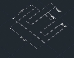
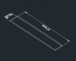
This project needs to use an aluminium core to identify the eddy current losses in the magnetic materials. In this process, the help of a technician is crucial since it involves a high-risk process that requires cutting and laminating the iron core. In order to do an aluminium choke, the E’s and I’s need to be done by using the aluminium material. The aluminium core designation was being done in the AutoCAD software in order to give precise detail about the design project.
Figure above shows the design of E’s and I’s in the AutoCAD software. The diameter of the measurement was taken by measuring the previous E’s and I’s of iron material. The thickness of the E’s and I’s is 1 mm of each block. The amount of aluminium E’s and I’s were around 30 blocks each. The aluminium choke can be created by stacking the aluminium of E’s and I’s on top of each other until there was no gap to be fill. Then, the aluminium core needs to be laminated and varnished. This was done in order to prevent any air gaps and current from flowing in between each block.
Design Iron Core
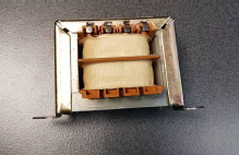
For the next design, the air core choke was replaced with an iron core choke to perform the same method of measurements and analysis that was done for the air-core choke. None of the circuit components were replaced to ensure the exact parameters that will be included in the measurements of the iron core choke. The iron core choke was obtained from the previous research project group.
Results
Choke Air-core
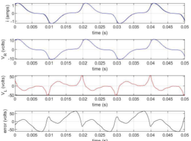
Those waveforms were the result after the bug found during the measurement has been fixed.
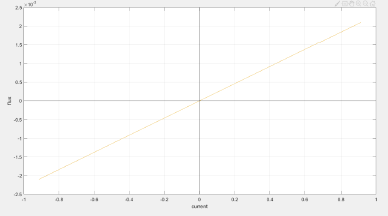
BH curve air core
The number of turns from the coil, the type of the material, and also the flow of the current along the coil affected the magnetic strength of the electromagnet. The B-H curve is the curve result on the flux density, B against the strength of the magnetic field, H. The ratio of flux density to field strength for ferromagnetic materials is not constant but contrasts with flux density. Since the result was from air core, this ratio was regarded as a constant, and this constant is known as free space permeability.
T-test
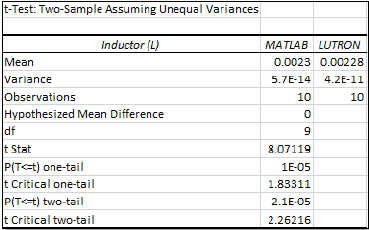
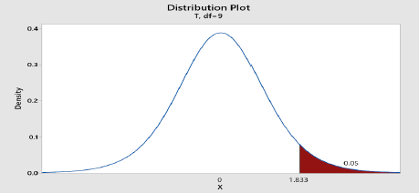
The result for t critical one tail analysis is stated in the figure above. 1.83311 is the t critical one tail value analysis which means that it is higher than the alpha value, 0.05. The value for the t critical one tail was 1.833 which cuts-off the alpha value at 0.05. The shape of the graph was affected by the value of degrees of freedom. The larger the degrees of freedom, the smaller the tails distribution area. Since the t critical one tail value is larger than the alpha value, thus the null hypothesis is accepted which there was no difference between both data.
Iron-Core
These waveforms were the reaction between the component inside the choke and the type of core material being used. These waveform results were affected by the value of the running voltage.
Aluminium-core Simulation
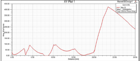
Both figures showed an identical waveform in which a sudden spike occurred at the 20mm length. This is due to the result that has been exceeding the length of the core at 20mm. when the waveform runs above the length of the core, a sudden spike on the flux density will be formed.
Conclusion
For the conclusion. This thesis focuses on the experiment that is being conducted throughout the period of this research project and the findings that were obtained with it. Studying the nonlinearities element of an inductor choke with a different type of material promotes the urge to obtain a better understanding of the properties of the magnetization and the electrical parameters that were being presented in the measurement, calculations, and the waveforms that were plotted.
All the calibration process on the tools and the main components for the research project is completed and the offsets of the that occurred have been obtained and taken into account in the calculations. The hypothesis testing that was conducted strengthens the level of comparison in two different methods of measuring the parameters in which the MATLAB calculations and the LUTRON LCR meter have been accepted as the there differences between the results are not significant and with the acceptance range.
The usage of Picoscope and MATLAB in the research project has been considered a successful approach as it provides required results in the measurement of the air core inductor choke and the iron core inductor choke. The magnetic properties of the air core inductor choke were obtained by creating the magnetisation curve which proves to be linear as the air core has no nonlinearities magnetic properties on it.
The simulation task that replaced the final measurement of the aluminium due to the unavoidable circumstances has been completed and analysed using the Ansys Maxwell software.
References
[1] C. Kittel, Introduction to solid state physics, 5th ed. New York: Wiley, 1976.
[2] J. P. A. Bastos, Magnetic materials and 3D finite element modeling. 2014.
[3] Y. Chen and P. Pillay, “An improved formula for lamination core loss calculations in machines operating with high frequency and high flux density excitation,” Conf. Rec. - IAS Annu. Meet. (IEEE Ind. Appl. Soc., vol. 2, pp. 759–766, 2002.
[4] L. O. Chua and K. A. Stromsmoe, “Lumped-Circuit Models for Nonlinear Inductors Exhibiting Hysteresis Loops,” IEEE Trans. Circuit Theory, vol. 17, no. 4, pp. 564–574, 1970.
[5] Y. Saito, S. Hayano, and Y. Sakaki, “A parameter representing eddy current loss of soft magnetic materials and its constitutive equation,” J. Appl. Phys., vol. 64, no. 10, pp. 5684–5686, 1988.
[6] G. Bertotti, “Hysteresis in Preisach Systems,” in Hysteresis in Magnetism, 1998.
