Projects:2021s1-13133 Optically Transparent Antenna System for 5G Mobile Application
Contents
Project Team
Students
- Dang Khoa Nguyen
- Zhaoqi Cui
Supervisors
- Dr. Nghia Nguyen-Trong
- Prof. Christophe Fumeaux
Introduction
Motivation
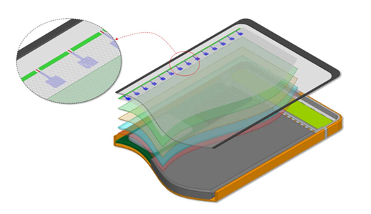
To utilise some of the latest features in 5G mobile network such as beam steering capability (pointing the main beam direction to different users to provide better signal coverage), which can only be achieved if a large number of antenna elements is implemented. Unfortunately, this task is extremely challenging due to limited space in modern handheld devices (as seen in Fig.1). A possible solution is to build an optically transparent antenna array which could be embedded in the view area of a mobile phone.
This project aims to design optically transparent antennas for mobile application. Through literature review, the project group explored different techniques to improve the antenna efficiency while keeping the transparency. Antenna simulations have been performed using industry-standard electromagnetic simulation software (Ansys HFSS), and two design prototypes were fabricated using Indium Tin Oxide (ITO) coated glass. The prototypes were tested with Vector Network Analyser and Anechoic chamber. The antenna-on-display concept[2] can be extended to a wide range of applications, such as antenna design for cars, windows and solar panels.
Objectives
- To explore different antenna design concepts as well as their challenges
- To design, fabricate and test optically transparent antenna designs with the following initial key expectations:
- Transparency: 60% - 70%
- Sheet Resistance: 1 - 2 Ω/sq
- Efficiency: 60% or higher
- Bandwidth: 2.45GHz - 5.8GHz
Background
But, what is an Antenna?
- A basic antenna system (Fig.2) consists of a power Source (sometimes called Feed), a Transmission Line (can be made using various materials) guiding the waves, and the Antenna transmitting or receiving radio waves.[3]
And the key expectations above, what do they mean?
- The key expectations can be divided into 2 categories: material and antenna performance expectations.
For the material of the antenna, the interesting terms are:
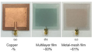
- Transparency: describes how transparent or see-through the material is. Shown below are a few examples of transparent materials, from opaque Copper to transparent Multilayer film and Metal-mesh film:
- The aim for transparency value is between 60% - 70%, so somewhere in between (b) and (c) above.
- Sheet Resistance: The classic resistance formula: resistance R (unit: Ohm) = resistivity ρ (rho) • (length L / area A).
- For a sheet: area A can be broken down into width W times by thickness t. Re-arranging the formula, we have resistivity ρ divided by thickness t, this term is called Sheet Resistance Rs. Sheet resistance has unit Ohm per square (often shortened to Ω/sq). It’s a compact and convenient property of a material, giving us its resistivity and thickness, without worrying about the size. Hence, it can be used to compare the electrical properties of devices that are significantly different in size. The project aims to have material with Sheet Resistance of 1 to 2 Ω/sq.
To describe antenna's performance, the following parameters are often used:
- Antenna (radiation) Efficiency: this measures how well an antenna converts accepted input power to radiated output power [Efficiency = Pradiated / (Pradiated + Ploss)]. The power loss (Ploss) could come from impedance mismatch or lossy antenna material.
- Reflection Coefficient (S11): the amount of power reflected by Antenna from the Source.
- Gain and Realized Gain: Gain describes how well the antenna converts input power into transmitting/receiving radio waves. Realized Gain is very similar, but its value also indicates how well matched an antenna is in terms of impedance (a well-matched antenna performs better), hence very useful and will be used in this project.
- It's important to know that high value of Gain or Realized Gain isn't always best for 5G mobile application, as we might want to avoid interference from certain frequencies.
- The mentioned parameters are typically presented in dB (deciBel unit). This is simply another way to represent ratio value:
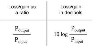
- e.g. If S11 = -10dB (or lower), that means the Antenna reflects back 10% of power (or less) from the Source.
- These performance terms are important because Efficiency measures how good an antenna design is (in terms of power loss), and S11 below -10 dB determines the Bandwidth (BW) of that antenna. A design that has high Efficiency and large BW means it's a wideband antenna (can be used in a wide range of frequencies) and has low power loss.
Previous Studies
Balancing Challenge
To explore why transparent antenna designs are not widely used, the project group conducted literature review on IEEE scientific papers on the topic from 2008-2020 [4] [5] [6] [7].
Through simulations and measurement results, they showed that highly transparent materials such as multilayer film and metal-mesh film (MMF), silver coated polyester film (AgHT) or Indium Tin Oxide (ITO), when compared to traditional Copper sheet (CS), they exhibit higher sheet resistance, which leads to lower antenna efficiency. Hence, for transparent antenna designs, there is an inherent trade-off between transparency and efficiency.
Proposed Solutions
There were two types of notable solutions to overcome the less-than-ideal property of transparent materials:
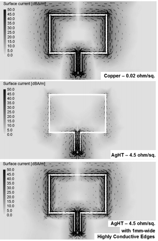
- Fig.3 shows the current density of a patch antenna made of copper, silver coated polyester film. There is ohmic loss along the slot edges due to the high sheet resistance. This indicates degradation in antenna performance. To counter this, the 2008 paper[6] proposed a method of applying a highly conductive coating in a very narrow strip to selective antenna areas of high current density. This improved efficiency of transparent film antenna, from 38% to 68% while preserving much of the transparency.
- The 2016 paper[7] applied the same concept, having gold nanolayers with various thicknesses deposited on the locations where the current density is high.
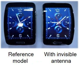
- Other proposed solutions in 2017-2019 followed the Antenna-on-display concept, using very fine conductive mesh as main material. This comes in the form of diamond-grid[2] or conductive wire grid polymers[8] (below, the watch to the right):
- These fine meshes come with their own set of problems, such as Moiré effect and optical haze. As well as require advanced fabrication techniques beyond this project's scope, and the resulting efficiency is not as high as the previous technique (about 41%[2] up to 52%[8]).
Methods
- Software: the antenna simulation software used for the project is HFSS[9] (High-Frequency Structure Simulator by ANSYS Electronics).
- Lab Tests: antenna lab results were obtained using digital sheet resistance measuring equipment, Vector Network Analyser (VNA) and Anechoic chamber at the University of Adelaide.
Vector Network Analyser shown in Fig.4 was used to test S11 parameters.
The Anechoic chamber was used to test antennas' performance. After placing the antenna on the turn-table, a Laser measuring instrument was used to determine the correct position and level between the transmitting horn antenna and the device to be tested. The turn-table makes a complete 360 sweep to determine the radiation pattern of the antenna. To calibrate the Anechoic chamber, use of standard horn antennas is required. By comparing the measured gain of the standard gain horn antenna and the gain corresponding to the prototype antenna itself, the measurement error of the anechoic chamber can be eliminated, and results normalised.
Design Process
Material
Indium Tin Oxide (ITO) was chosen as main material for the project due to advantages it provides:
- Relatively easy to purchase and fabricate
- Good trade-off between Transparency and Sheet Resistance
- Small footprint
- Suitable for 5G applications
Specifications of ITO etched glass used for the transparent design prototypes:
- Size: 50mm x 50mm x 1.1mm (length x width x thickness)
- Sheet Resistance: 1.5 Ω/sq
- ITO transparency: 70%
- Glass transparency: up to 92%
- Glass dielectric constant: 5.5 - 6
Designs
The project team devised 2 separate transparent antenna designs:
- A wideband patch antenna array: consists of ITO etched glass layer, transparent dielectric substrate layer and a copper ground plane.
- This design aims to take the advantage of good S11 result of traditional patch antenna, which is simple to design (Fig.8). Though it can be seen that the the resulting S11 band below -10dB is very narrow. To widen the bandwidth, U-slot cut out is added to the antenna element. This modification is based on the design proposed in [10], combined with the array layout of antenna-on-display concept [2]. The detailed measurement of the design is displayed in Fig.9.
- An ultra wideband monopole antenna: the broadband antenna design used is a CPW (Coplanar waveguide) structure. This means that the patch is on the same plane as the ground. According to the published literature [11], it was found that the round patch can better form broadband. And the circular ground will resonate with the circular patch, which can widen the bandwidth. The design is laid out in Fig.10.
The ITO-etched layer of both transparent antenna designs are shown below with Dang’s design (left) and Zhaoqi’s design (right). They are laid on top of paper with graphics to show the (estimated) transparency: 92% and 80%, respectively. This satisfies the project's transparency requirement.
Results and Measurements
Simulated Results
Fig.11 (right) show simulated S11 (reflection coefficient) results of the two prototypes (wideband antenna in red, and U-slot patch array in blue). The results show the intended frequency for each design (below -10dB). The red line in Figure 11 shows the S11 curve of the broadband antenna. The value of S11 from 1.43GHz to 8GHz is less than -10dB, which means that the return loss from 1.43Ghz to 8GHz is less than 10%.
Fig.12 shows the average efficiency:
- U-slot patch array: the simulated S11 result shows the bandwidth widening effect as expected, the design can operate at 5.37GHz - 6.43GHz.
- A change in transparent dielectric substrate layer from glass to polystyrene plastic (commonly found on optical disc jewel cases) saw some changes in the performance of the design. The central operating frequency shifted from the original 5.8GHz to 6.4GHz, coupled with a slight increase of efficiency: from an average of 31.6% (glass substrate) to 37.95% (polystyrene). This shows the design's potential flexibility, being able to be used on various transparent materials, and can be optimised for different desired frequency.
- WB antenna: Figure 12 shows the efficiency of the broadband antenna. It can be seen that the average efficiency of the design between 1GHz and 8GHz is about 67%.
The realized gain (co-polarisation and cross-polarisation) results of U-slot patch array, with polystyrene substrate is shown in Fig.13 (below).
The simulation results show promise for real-world use, as well as emphasize the balance between high efficiency and optical transparency between the two designs.
Lab Measurements
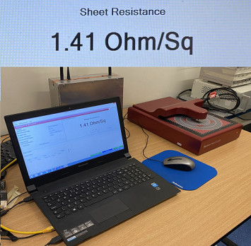
Using digital measuring equipment, the sheet resistance of the ITO glass was measured to be:
This measurement satisfied the project's objective of having sheet resistance between 1 - 2 Ω/sq. And with low measured sheet resistance, good antenna efficiency can be expected. This also influences the antenna bandwidth.
The results can be observed in Fig.14 and Fig.15 (right). The simulated and measured S11 parameters below -10dB were shown to match, and indicate that the antennas can be used within the expected frequency ranges.
The prototypes' gain and radiation pattern results are currently being analysed and confirmed, but initial measurements have lined up with expectations thus far. The project team expect the prototypes shall perform well, though can be further improved.
Figure 16 is the radiation pattern diagram of the broadband antenna designed by zhaoqi‘s at 2.45GHz and 5.8GHz.In the four pictures a, b, c, d, the red line represents the simulation result, and the blue line represents the actual measurement result. It can be seen that most of the tested gain graphs match the simulated graphs. The few gain graphs that are not well matched may be caused by the environmental noise during the test. By observing the image shown in Figure 16, which shows that the antenna is an omnidirectional antenna. Comparing Figure 16 (a)and (b) with 16(c) and (d), the cross-polarized radiation at 5.8GHz is a little larger than those at 2.45GHz, this phenomenon often occurs at high working frequency.
Conclusion
- The project team has completed the entirety of antenna design process, from exploring antenna theory, design requirements, simulation, fabrication to lab testing, and satisfied the list of project objectives.
- Fabricated 2 transparent antenna prototypes, the designs show promising and viable simulation results, and each can be modified and improved to suit different applications and needs.
- One antenna design has high efficiency (67% on average) and can operate from 1GHz-8GHz.
- The other has high optical transparency of up to 92% (top layer) hence can be applied on display of mobile devices, but in turn has lower efficiency (31%-37%) and narrower bandwidth (5.3GHz-6.4GHz for glass substrate, 6GHz-7.5GHz using polystyrene plastic substrate).
- Initial confirmed lab test results agree with simulated expectations and show that the antenna can be used for intended frequency bands.
- Concept can be extended to a wide range of real-world applications (any transparent surface could be used as an antenna!).
References
- ↑ Samsung Australia. 2021. Galaxy S21, S21+ S21 Ultra: Device Layout. [online] Available at:<https://www.samsung.com/au/support/mobile-devices/s21-device-layout-and-functions/>
- ↑ 2.0 2.1 2.2 2.3 2.4 J. Park, S. Lee, J. Kim, D. Park, W. Choi and W. Hong, "An Optically Invisible Antenna-on-Display Concept for Millimeter-Wave 5G Cellular Devices", IEEE Transactions on Antennas and Propagation, vol. 67, no. 5, pp. 2942-2952, 2019. Available: 10.1109/tap.2019.2900399.
- ↑ 3.0 3.1 Balanis, C., 2005. Antenna theory: Analysis and Design. 3rd ed. Wiley-Interscience, pp.1-2.
- ↑ S. Hong, Y. Kim and C. Won Jung, "Transparent Microstrip Patch Antennas With Multilayer and Metal-Mesh Films", IEEE Antennas and Wireless Propagation Letters, vol. 16, pp. 772-775, 2017. Available: 10.1109/lawp.2016.2602389.
- ↑ P. Duy Tung and C. Jung, "Optically Transparent Wideband Dipole and Patch External Antennas Using Metal Mesh for UHD TV Applications", IEEE Transactions on Antennas and Propagation, vol. 68, no. 3, pp. 1907-1917, 2020. Available: 10.1109/tap.2019.2950077.
- ↑ 6.0 6.1 6.2 Hyok Jae Song, Tsung Yuan Hsu, D. Sievenpiper, Hui Pin Hsu, J. Schaffner and E. Yasan, "A Method for Improving the Efficiency of Transparent Film Antennas", IEEE Antennas and Wireless Propagation Letters, vol. 7, pp. 753-756, 2008. Available: 10.1109/lawp.2008.2008107.
- ↑ 7.0 7.1 7.2 M. Haraty, M. Naser-Moghadasi, A. Lotfi-Neyestanak and A. Nikfarjam, "Improving the Efficiency of Transparent Antenna Using Gold Nano Layer Deposition", IEEE Antennas and Wireless Propagation Letters, pp. 4-7, 2016. Available: 10.1109/lawp.2015.2424918.
- ↑ 8.0 8.1 8.2 W. Hong, S. Lim, S. Ko and Y. Kim, "Optically Invisible Antenna Integrated Within an OLED Touch Display Panel for IoT Applications", IEEE Transactions on Antennas and Propagation, vol. 65, no. 7, pp. 3750-3755, 2017. Available: 10.1109/tap.2017.2705127.
- ↑ "Ansys HFSS | Ansys Electronics", Ansys.com, 2021. [Online]. Available: https://www.ansys.com/products/electronics/ansys-hfss
- ↑ H. Wang, X. Huang and D. Fang, "A Single Layer Wideband U-Slot Microstrip Patch Antenna Array", IEEE Antennas and Wireless Propagation Letters, vol. 7, pp. 9-12, 2008 [Online]. Available: https://ieeexplore.ieee.org/stamp/stamp.jsp?tp=&arnumber=4400941
- ↑ M. R. Haraty, M. Naser-Moghadasi, A. A. Lotfi-Neyestanak and A. Nikfarjam, "Improving the Efficiency of Transparent Antenna Using Gold Nanolayer Deposition," in IEEE Antennas and Wireless Propagation Letters, vol. 15, pp. 4-7, 2016, doi: 10.1109/LAWP.2015.2424918.
