Difference between revisions of "Projects:2016s1-146 Antonomous Robotics using NI MyRIO"
(→Localisation System) |
|||
| (35 intermediate revisions by 4 users not shown) | |||
| Line 1: | Line 1: | ||
== Introduction == | == Introduction == | ||
| − | + | The aim of this project was to design and construct an autonomous robot that incorporated the following attributes: | |
| + | * Localisation – Knowing the robot’s position. This allows the robot to move precisely within the map. | ||
| + | * Obstacle Avoidance – Detecting and avoiding any nearby stationary objects. This allows the robot to move safely as it traverses the map. | ||
| + | * Object Handling – Transport and safe delivery of objects to specific locations. This allows the robot to deposit packages to specific locations within the map. | ||
| + | * Path Planning – Determining the best path to achieve the current objective. This allows the robot to dynamically make decisions about the path to take within the map | ||
== Supervisors == | == Supervisors == | ||
| Line 23: | Line 27: | ||
LabView programming knowledgement would be a key advantage in this project. | LabView programming knowledgement would be a key advantage in this project. | ||
This project builds on the platform designed and built in 2015 | This project builds on the platform designed and built in 2015 | ||
| + | |||
| + | [[File:NI_flyer.png|frameless|center|upright=1.7]] | ||
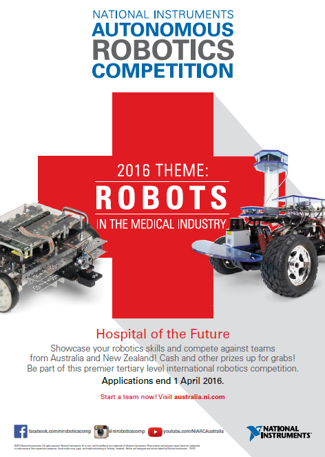
| + | <center>Figure 1: National Instruments flyer</center> | ||
== Project Proposal == | == Project Proposal == | ||
| Line 28: | Line 35: | ||
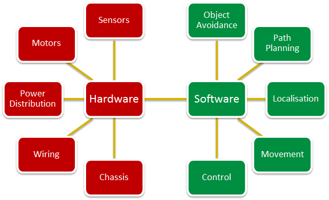
To have a better understanding of the project and to distribute the workload amongst the team, the robot system has been broken down into the following sections: | To have a better understanding of the project and to distribute the workload amongst the team, the robot system has been broken down into the following sections: | ||
| − | Mechanical Construction Artificial Intelligence (Software) | + | * Mechanical Construction |
| + | * Artificial Intelligence (Software) | ||
| + | * Robot Vision and Range Finding | ||
| + | * Localisation | ||
| + | * Movement system | ||
| + | * Hardware design | ||
| + | * Medicine dispenser unit | ||
| + | * Pathfinding/Navigation Control | ||
| + | * Object detection | ||
| + | * Mapping Movement tracking | ||
By creating a set of clearly defined work activities, each team member will be able to design and develop the required functionality for their respective sections. | By creating a set of clearly defined work activities, each team member will be able to design and develop the required functionality for their respective sections. | ||
| + | |||
| + | [[File:Design_poster_layout.png|frameless|center|upright=2.5]] | ||
| + | <center>Figure 2: System design chart</center> | ||
The mechanical construction will focus on the design and assembly of the robot itself. This process will involve deciding on the robot dimensions, motors, sensors and medicine delivery system. Current research and development has been made to the movement system and a four omnidirectional wheeled approach is being prototyped. This prototype will demonstrate a robot with the ability to move in any direction easily without the need to rotate before any translation takes place. Figure 1 shows the layout that will be used for this robot design. The mechanism for delivering the medicine units shall be similar to the design from last year’s University of Adelaide team. Figure 2 demonstrates how this medicine delivery shall work. | The mechanical construction will focus on the design and assembly of the robot itself. This process will involve deciding on the robot dimensions, motors, sensors and medicine delivery system. Current research and development has been made to the movement system and a four omnidirectional wheeled approach is being prototyped. This prototype will demonstrate a robot with the ability to move in any direction easily without the need to rotate before any translation takes place. Figure 1 shows the layout that will be used for this robot design. The mechanism for delivering the medicine units shall be similar to the design from last year’s University of Adelaide team. Figure 2 demonstrates how this medicine delivery shall work. | ||
| Line 40: | Line 59: | ||
[[File:Wheel Layout.png|center]] | [[File:Wheel Layout.png|center]] | ||
| + | [[File:Medicine delivery system.png|center]] | ||
| + | |||
| + | [[File:NI_Track_setup.png|center]] | ||
| + | |||
| + | == Milestones == | ||
| + | As part of the project the team was required to complete milestones as requested by National Instruments to remain in the competition. The following table summarises the milestones that were completed. | ||
| + | |||
| + | [[File:Milestone chart.png|center]] | ||
| + | <center>Figure 3: National Instruments milestone chart</center> | ||
| + | |||
| + | Below is the work that was completed for each Milestone. | ||
| + | |||
| + | * Milestone 1: (27th April) | ||
| + | ** Completion of the Online NI LabVIEW Training Course (Core 1 and Core 2) by two team members. | ||
| + | |||
| + | * Milestone 2: (9th May) | ||
| + | ** Submit Project Proposal (300-500 words in MS Word or MS PPT format) | ||
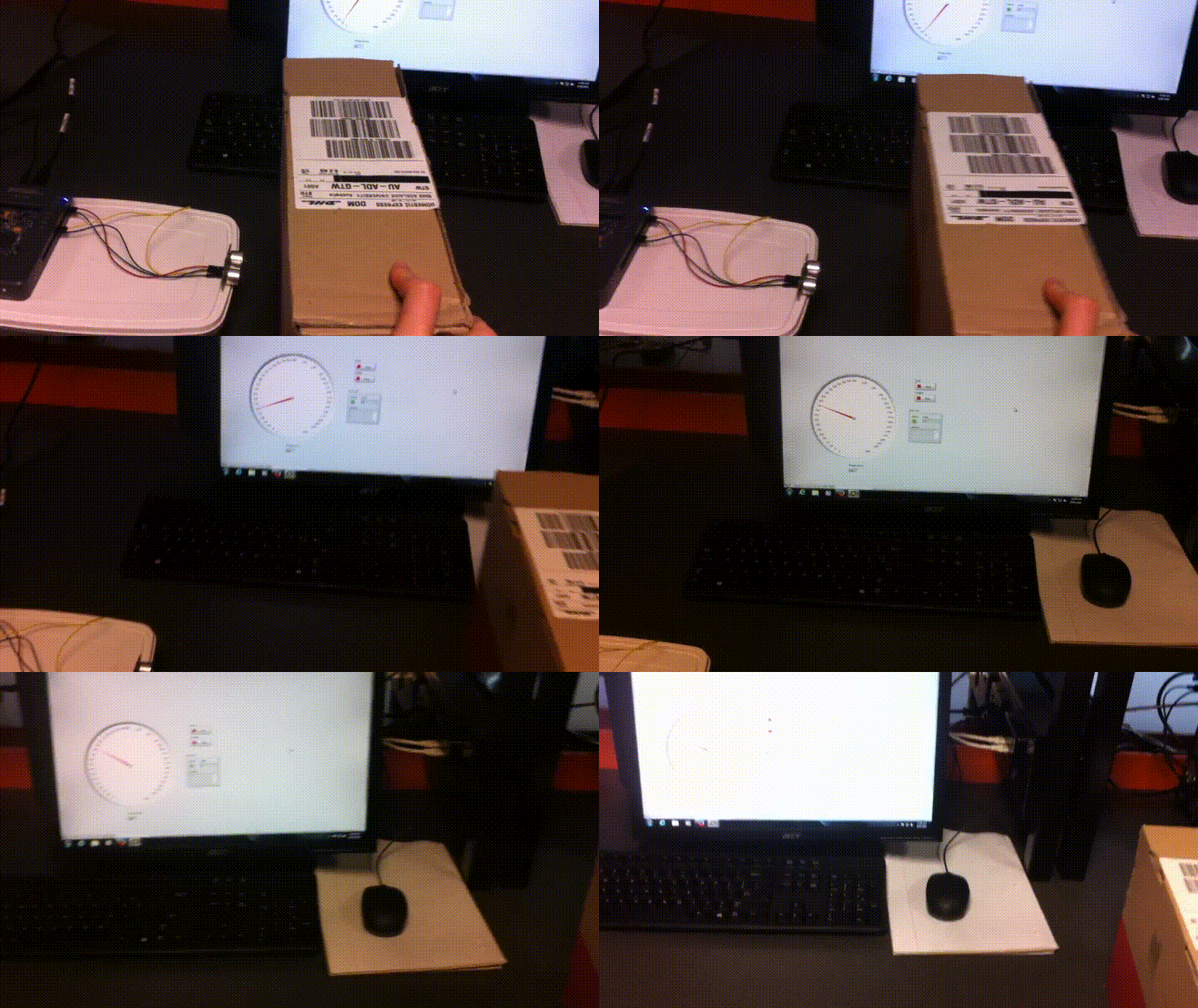
| + | ** Demonstrate usage of NI myRIO and LabVIEW to control at least one actuator/motor or acquire from at least one sensor. | ||
| + | |||
| + | [[File:Milestone 2 - Motor Control.gif|center]] | ||
| + | <center>Figure 4: Milestone 2 - Motor Control</center> | ||
| + | |||
| + | [[File:Milestone 2 - Servo Control.gif|center]] | ||
| + | <center>Figure 5: Milestone 2 - Servo Control</center> | ||
| + | |||
| + | [[File:Milestone 2 - Ultrasonic sensor.gif|center]] | ||
| + | <center>Figure 6: Milestone 2 - Ultrasonic sensor</center> | ||
| + | |||
| + | * Milestone 3: (8th June) | ||
| + | ** Requirement: Preliminary design and prototype with obstacle avoidance implemented. | ||
| + | ** Demonstrate: Create a prototype that moves forward avoiding obstacles. | ||
| + | |||
| + | [[File:Milestone 3 - Linear Object avoidance.gif|center]] | ||
| + | <center>Figure 7: Milestone 3 - Linear Object avoidance</center> | ||
| + | |||
| + | * Milestone 4: (25th July) | ||
| + | ** Requirement: Demonstration of navigation/localisation and obstacles avoidance. | ||
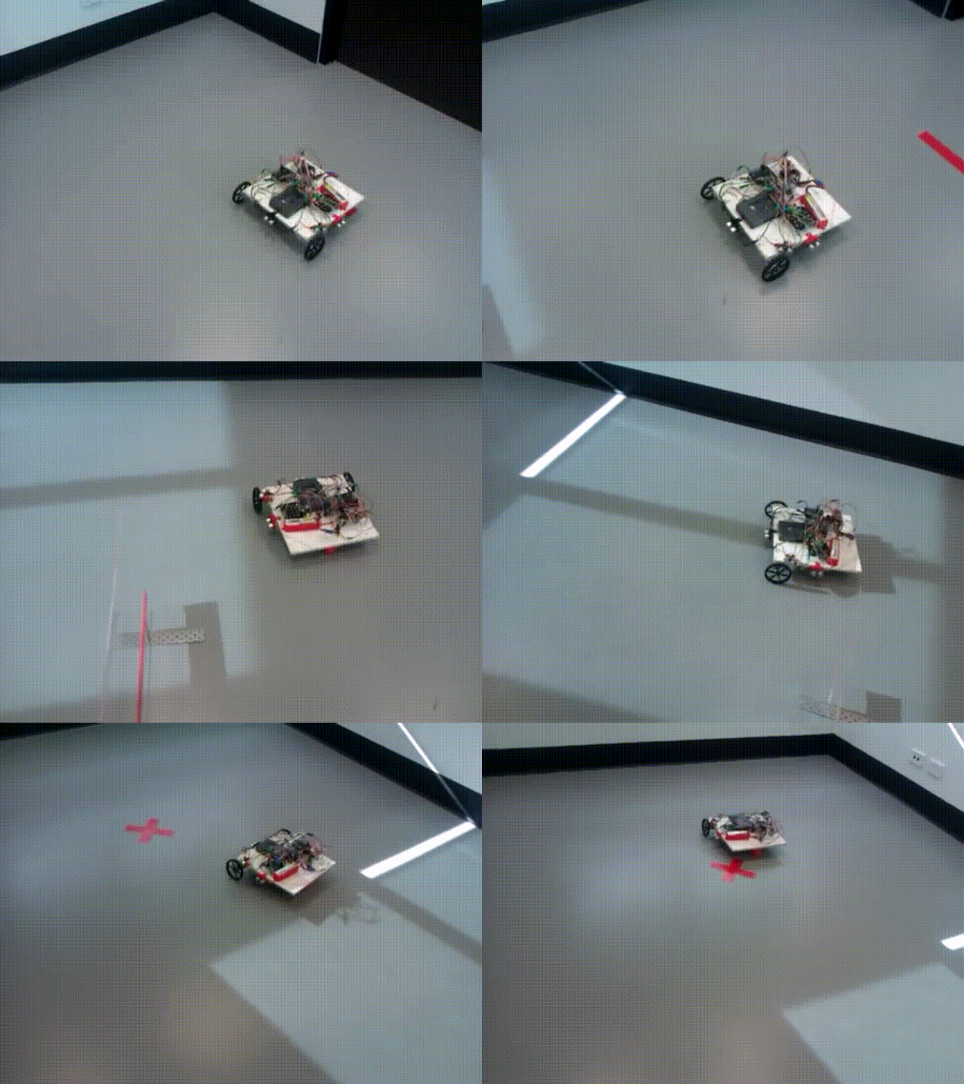
| + | ** Demonstrate: Robot begins with loaded medicine units in location A and then moves to location B. At location B, the robot carefully places a single medicine unit on an elevated space (a platform higher than the ground the robot is on). | ||
| + | |||
| + | [[File:Milestone 4 - Navigation and Unloading Medicine Unit.gif|center]] | ||
| + | <center>Figure 8: Milestone 4 - Navigation and Unloading Medicine Unit</center> | ||
| + | |||
| + | * Milestone 5: (29th August) Requirement to Qualify for Finals. | ||
| + | ** Requirement: Object handling, navigation and obstacle avoidance. | ||
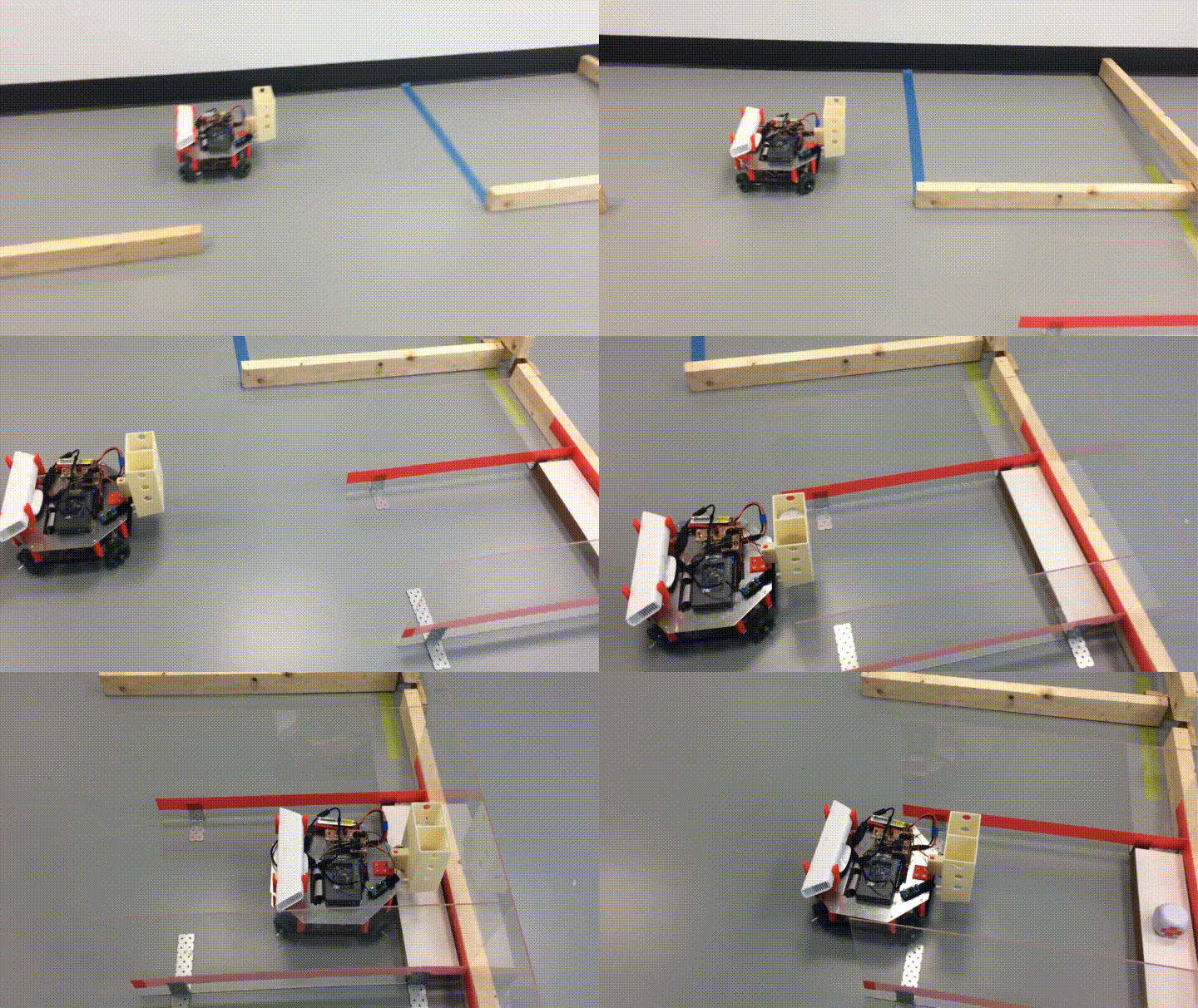
| + | ** Demonstrate: Move from location A (with loaded medicine units) to location B while avoiding obstacles. At location B, the robot carefully places a single medicine unit on an elevated platform (a platform higher than the ground the robot is on). The robot then moves to location C while avoiding obstacles to place another medicine unit on another elevated platform. Finally, the robot must move to location D while avoiding obstacles to finish the task. | ||
| − | [[File: | + | [https://www.youtube.com/watch?v=iR7q4NpT-XA Milestone 5 video] |
| + | |||
| + | To see any of the above videos in full please visit [https://www.youtube.com/channel/UCtABluvLFFNrf11aLboNYpA Team MEDelaide's Channel] | ||
| + | |||
| + | == Project Outcomes == | ||
| + | |||
| + | The outcomes for each of the major systems has been documented below. | ||
| + | |||
| + | === Prototypes and Final Robot === | ||
| + | |||
| + | ---- | ||
| + | |||
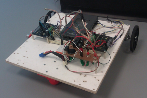
| + | Throughout the course of this project two prototypes and a final robot product was developed. Initially, the first prototype was developed as a simple two wheeled robot which the team could use to experiment on and learn from.It was constructed from a single 300 x 300mm wooden base which various wheels and sensors were attached to. | ||
| + | |||
| + | [[File:First Prototype.png|frameless|center|upright=2]] | ||
| + | <center>Figure 9: First prototype</center> | ||
| + | |||
| + | After some research and progress through the early stages of the project a more advanced prototype was created. This version consisted of a 4 omni-wheeled setup. The reason this setup was chosen was to enable the robot to move in any desired direction simply and efficiently. | ||
| + | |||
| + | [[File:Second_Prototype.jpg|frameless|center|upright=2]] | ||
| + | <center>Figure 10: Second prototype</center> | ||
| + | |||
| + | Finally, after the majority of research was done by all team members and a greater understanding of the capabilities of the previous prototypes the final robot was first designed and then constructed. | ||
| + | |||
| + | [[File:011_DomeAttached.jpg|frameless|center|upright=2]] | ||
| + | <center>Figure 11: Final build robot</center> | ||
| − | + | To view a more detailed breakdown of the process in designing and constructing final robot please click the link to 'Robot Construction' below. | |
| + | [[Robot Construction]] | ||
=== Movement System === | === Movement System === | ||
| − | + | ---- | |
| − | + | The movement system incorporates all of the control in relation to the motors that turn the four omnidirectional wheels. This control consists of acceleration and deceleration to reduce sliding when starting or ending a movement. It also includes a fail safe which utilises ultrasonic sensors to allow the motor speeds to be reduced or stopped if the robot becomes too close to any nearby object. To reduce the robot veering off course a motor ‘balancing algorithm’ was developed to use the motors inbuilt encoders to determine the distance traveled by each individual motor and scale the speeds of each motor accordingly. | |
| − | + | ==== Balancing Algorithm ==== | |
| − | + | The motor balancing algorithm is the name given to the subsystem which scales each motor’s PWM values automatically while the robot is completing a movement command. Pulse Width Modulation (PWM) is a technique for achieving analog results with digital techniques. Digital control is used to create a square wave where the signal can be switched on and off. A common term used in PWM communication is ‘duty cycle’. Duty cycle is usually expressed as a percentage, it describes the ratio of time spent at a high voltage and low voltage. As can be seen from the figure below the duty cycle of the first sub plot is 25% therefore the signal is high 25% of the time and low 75% of the time. | |
| − | [[File: | + | [[File:pwm_example.png|frameless|center|upright=2]] |
| + | <center>Figure 12: PWM and duty cycle example<ref>https://www.rmcybernetics.com/blog/basic-pwm-explanation/</ref></center> | ||
| − | + | The motor balancing algorithm was invented to reduce the impact of any calibration issues and allow a rough calibration to be performed as the robot is operating. It starts by taking in the current encoder readings from each motor and comparing them to find if the robot is deviating to the left or right of its current path. After the deviation direction is located the motors are scaled either up or down to correct the robot back to the desired path. | |
| − | The | + | The results of this process can be seen in the video below. |
| + | [[File:Movement_control_balancing_algorithm_1.gif|center]] | ||
| + | <center>Figure 13: Motor control without balancing algorithm</center> | ||
| − | + | [[File:Movement_control_balancing_algorithm_2.gif|center]] | |
| + | <center>Figure 14: Motor control with balancing algorithm</center> | ||
| − | |||
=== Localisation System === | === Localisation System === | ||
| + | |||
| + | ---- | ||
| + | |||
The localisation system is built on optical flow, and computer vision. Optical flow provides a high update rate but is susceptible to noise and accuracy drift. Computer vision observations are registered to the competition track. While the update rate is much lower, it has zero drift. A hybrid was built to obtain a fast update rate from the optical flow system, while counteracting drift errors with the computer vision system. Both these components are described in the following sections. | The localisation system is built on optical flow, and computer vision. Optical flow provides a high update rate but is susceptible to noise and accuracy drift. Computer vision observations are registered to the competition track. While the update rate is much lower, it has zero drift. A hybrid was built to obtain a fast update rate from the optical flow system, while counteracting drift errors with the computer vision system. Both these components are described in the following sections. | ||
| Line 72: | Line 168: | ||
[[File:adns9800_top_and_bottom.png|center|500px|thumb|alt=ADNS-9800 Optical flow sensor module.|ADNS-9800 Optical flow sensor module.]] | [[File:adns9800_top_and_bottom.png|center|500px|thumb|alt=ADNS-9800 Optical flow sensor module.|ADNS-9800 Optical flow sensor module.]] | ||
| − | The optical flow system was analysed through simulation in MATLAB (see the figure below for an example of the output). This | + | The optical flow system was analysed through simulation in MATLAB (see the figure below for an example of the output). This confirmed the drift errors mentioned earlier. Furthermore, it was found that discrepancies between sensor measurements of approximately 10mm was enough to cause heading errors of up to 8 degrees, and position errors up to 46cm and 70cm along x and y in the global coordinate system. This affirmed the need for the drift correction system. |
[[File:MATLAB_simulation_output.png|center|1000px|thumb|alt=Simulation output in MATLAB. The green line is that actual trajectory, the blue line is the trajectory estimated from the optical flow sensors with noise to simulate real life sensors.|Simulation output in MATLAB. The green line is that actual trajectory, the blue line is the trajectory estimated from the optical flow sensors with noise to simulate real life sensors.]] | [[File:MATLAB_simulation_output.png|center|1000px|thumb|alt=Simulation output in MATLAB. The green line is that actual trajectory, the blue line is the trajectory estimated from the optical flow sensors with noise to simulate real life sensors.|Simulation output in MATLAB. The green line is that actual trajectory, the blue line is the trajectory estimated from the optical flow sensors with noise to simulate real life sensors.]] | ||
| Line 80: | Line 176: | ||
[[File:OF_sensor_placement.png|center|350px|thumb|alt=Placement of the ADNS-9800 sensor modules.|Placement of the ADNS-9800 sensor modules.]] | [[File:OF_sensor_placement.png|center|350px|thumb|alt=Placement of the ADNS-9800 sensor modules.|Placement of the ADNS-9800 sensor modules.]] | ||
| − | Through experimentation | + | Through experimentation with the sensors, it was found that three levels of calibration were required. Firstly, the resolution of the sensors must be found. The resolution is affected by the height it is mounted above the ground, and the angle which the laser projects to the surface. As the sensor height above ground is increased, it's effective resolution is decreased. When the height is decreased, the resolution increases until it reaches the resolution configured in the device. Since the sensors are suspended above the ground, the resolution must be calibrated. |
| + | |||
| + | For the second factor, the angle of the laser sensor causes the resolutions to vary depending on the direction of translation. It was found that motion of a fixed distance along the positive y-axis was measured slightly greater than the same distance but along the negative y-axis. This also held true for the x-axis. This result meant that 4 resolution calibration factors were ideally required. In practice it was found that only one per x and y axis was sufficient. | ||
| + | |||
| + | The next level of calibration was for the angular and displacement offsets of the sensors - theta, phi and r components (see the picture below). For higher accuracy these offsets were measured through data collection, and resolving the constants from the 3DOF estimation equation. In this step, the robot was moved in fixed translations and rotations. The algorithm in LabVIEW used this recorded data to solve for the offsets. | ||
| + | |||
| + | The highest level of calibration scaled the translations along the x and y axis as well as rotations to ensure that distances and angles were measured accurately. As hinted in the first level of calibration, the robot's measurements differ between +y and -y translations, and +x and -x translations. These measurements were calibrated so positive and negative movements along the x and y axes were equal. | ||
| + | |||
| + | [[File:coordinate_frames.jpg|center|350px|thumb|alt=Coordinate frames and calibration offsets explained.|Coordinate frames and calibration offsets explained.]] | ||
| + | |||
| + | Using the calibrated offsets and data from the sensors, the position and heading changes of the robot are found using the equation shown below. | ||
| + | |||
| + | [[File:OF_equations.png|center|1000px|thumb|alt=Equations to solve for the robot's motion.|Equations to solve for the robot's motion.]] | ||
| + | |||
| + | ==== Computer Vision System ==== | ||
| + | The computer vision system was built on the range data produced by the Xbox Kinect. See the Xbox Kinect section for more details. | ||
==== Heading Correction System ==== | ==== Heading Correction System ==== | ||
| + | As seen in the simulation data previously, the heading of the optical flow system is inaccurate and greatly effected by measurement errors. In practice this was also found to be the case. From testing, the heading was found to be far too inaccurate for use. For instance, the average drift over 1.5m was 30 degrees. The resulting accumulated position errors of the robot were therefore 20cm per meter. | ||
| + | |||
| + | In each case, it was found that while the heading estimation was greatly effected by the measurement errors, the translation estimation was not (see figure (c) in the MATLAB simulation picture above). At this stage, an inertial measurement unit (''IMU'') could have been added to the system to provide a more reliable source of heading. Due to the competition nearing only one month away, a new tactic involving the Xbox Kinect and motor control was used instead of the IMU. | ||
| + | |||
| + | It was found that by allowing the robot to move without rotations, the robot's position estimation in the robot's local coordinate frame, with a fixed assumed heading could be used. The motor controller managing translations was designed to move the robot with minimal heading changes. To correct for slight heading drifts, and to ensure the robot stays on path, the Xbox Kinect was used to align the robot to key points around the track. More information on the Xbox Kinect alignment can be found in the appropriate section on this page. | ||
| + | |||
| + | ==== Conclusion ==== | ||
| + | The end solution of the localisation system differed from the initial plan in that heading was not measured in the final system, and there was a heavy dependence on the performance of the motor controller. Even with the issues discovered while designing and testing the system, the localisation system was able to successfully measure transnational distances within the accuracy required by the project. | ||
| + | |||
| + | Future improvements for the localisation system would involve; | ||
| + | * Investigate using an IMU for heading measurements, and combine this with the translation estimation from the optical flow sensors. | ||
| + | * Improve the computer vision system to correct position as well as heading. | ||
| + | |||
| + | |||
| + | === Vision System === | ||
| + | |||
| + | ---- | ||
| + | |||
| + | ==== Xbox 360 Kinect Camera ==== | ||
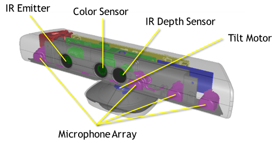
| + | The vision system for this project utilises a Microsoft Kinect RGB-D camera for obstacle mapping and wall alignment purposes. A breakdown of this camera can be seen below on the left, followed by the configuration in which the camera is mounted onto the robot on the right. | ||
| + | |||
| + | [[File:Kinect.png|left|thumb|575px|Hardware Breakdown of Kinect <ref>Microsoft, “Kinect for Windows Sensor Components and Specifications,” Microsoft, 2016. [Online]. Available: https://msdn.microsoft.com/en-us/library/jj131033.aspx. [Accessed 2 June 2016]</ref>]] | ||
| + | [[File:Kinect on Robot.JPG|right|thumb|720px|Position of Kinect Camera on Robot Chassis]] | ||
| + | |||
| + | <br /><br /><br /><br /><br /><br /><br /><br /><br /><br /><br /><br /><br /><br /><br /><br /><br /><br /> | ||
| + | |||
| + | This project primarily uses the IR camera output to produce depth readings in a 3D space (see followings subsections for explanation). | ||
| + | |||
| + | ==== Obstacle Mapping ==== | ||
| + | The method for mapping obstacles from the Kinect's depth readings involves two steps: lens distortion correction, and rotation and translation. To see an in-depth explanation of these methods, click [[Projects:2016s1-146 Antonomous Robotics using NI MyRIO - Vision Method|here]]. | ||
| + | To demonstrate the outcome of applying these methods using LabVIEW on the myRIO device, a data set was captured of boxes placed in a room corner. The set of images below show: the colour image of the capture (left), the 3D plot of the data created from the IR camera readings (middle), and the corresponding 2D obstacle map. | ||
| + | |||
| + | [[File:Boxes obstacles.jpg|center|thumb|1200px|Creating Obstacle Mapping of Boxes]] | ||
| + | |||
| + | |||
| + | ==== Wall Alignment ==== | ||
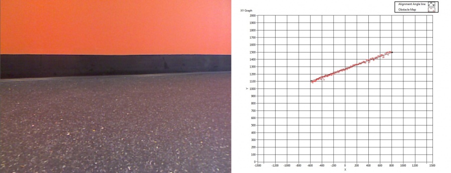
| + | The primary use of the 2D obstacle map is to perform wall alignment rotations in order to correct for heading drift in the movement system. The image below demonstrates how this is realised, with the colour capture of a wall on the left, and the corresponding obstacle map (shown as red data points) with measured alignment angle (shown as black line) on the right. | ||
| + | |||
| + | [[File:Wall alignment.jpg|center|thumb|900px|Example of Wall Angle Measurement]] | ||
| + | |||
| + | The movement system can then perform rotations by this measured angle to result in the robot facing the desired wall. | ||
| + | |||
| + | === Path Planning === | ||
| + | |||
| + | ---- | ||
| + | |||
| + | The path planning | ||
| + | The development of the autonomous robot is moving fast and plays significant roles in science and manufacturing fields. An autonomous robot is a robot that is able to perform tasks by its own; particularly they are designed in certain areas and fields. The robot is able to perform repetitive tasks while it can make its own decisions to make sure it do not damage any object or human or be damaged in unexpected situations. For example, famous autonomous vehicle NASA Mars Rover Opportunity and Spirit can make their own decisions to make additional observation of rocks by using their camera sensors to check the rocks that satisfy certain criteria.The trending of autonomous robot expands on many fields, such as in logistics delivering goods, military combat situations and manufacture goods. In the future, it is expected that the autonomous robot take over low skill labour jobs, so people can focus in more senior level of work. | ||
| + | |||
| + | Many researchers across the world are working on the path planning algorithm of autonomous robot. Numeral algorithms have been invented and further improved to calculate optimal path(shortest path) from start area to target areas without collision with obstacles. In this Project, pointBug path planning algorithm is used and implemented in LabVIEW for the autonomous robot system. | ||
| + | |||
| + | PointBug algorithm is a point to point path planning algorithm. It plans the path based on the readings from Kinect camera sensor and from start point to target point. The Kinect camera sensor returns magnitudes and angles in the one dimensional array form. Because the readings from Kinect are randomly allocated and cumbersome, a technic of data reduction is used to illuminates all the useless and meaningless data such zeros or NaN(Not a Number) in magnitudes and angles arrays. Next, the order of angles array is sorted so the element from the array starts at 68 degree to 111 degree. Then many similar values are filtered out and only use one of the set of similar values to represent the rest ones. Each element in magnitudes array was corresponding to the element in angles array in the same order. At this stage, the elements in these two arrays are much smaller and all arrays are in order to ease the process for the path planning algorithm. | ||
| + | |||
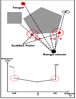
| + | The robot uses its sensors to check special points called sudden point. A sudden point is a point that the sensor detects change from the nearest obstacle to free space. To help to understand the concept, the figure below is used to explain the sudden point. | ||
| + | |||
| + | [[File:Sudden Point.png|center]] | ||
| + | |||
| + | The pointBug algorithm checks adjacent value in magnitudes array starting at the first element of the array, which was also corresponding to the first element of angles array.If there was 50cm difference between two adjacent readings from Lidar sensor, then a sudden change was detected. Then the algorithm determined the sudden point by first analyzing which point was closer to the robot between two adjacent sensor readings with 50cm difference between two values. The sudden point was chosen as the point that was further away from the robot and also the closest toward target point. If the sudden point was on the left of the obstacle that had been detected, the robot chose to go to the point more left to travel in order to safely avoid the obstacle, because there were 5-degree gap of Lidar sensor readings and there could be obstacle in the 5-degree gap. In the similar manner, if the sudden point was on the right of the obstacle that had been detected, the robot chose to go to the point more right. If there is no sudden point found, then the robot determines that the target is unreachable and it stops. | ||
| + | |||
| + | However, this path planning algorithm is not used in the project because it needs accurate measure of the current position of the robot from localisation system. It is also found that the assumption of determining whether the target is reachable or not is wrong. The detecting range of the Kinect is only 43 degree, which is considerably small compared to other sensors. The potential sudden point can be at outside of the detaching range of the Kinect camera sensor. | ||
| + | |||
| + | '''Conclusion''' | ||
| + | |||
| + | The pointBug algorithm is implemented in LabVIEW and tested to find the correct way point (sudden point ) to travel in order to reach the final destination point. The further work involves letting the robot to turn a certain degrees to get readings from the Kinect sensor to find the sudden point for the robot to travel to avoid collision with obstacle. Until the robot turns 360 degrees, the robot determines that the target point is unreachable and it stops. | ||
== References == | == References == | ||
| + | <references /> | ||
Latest revision as of 11:53, 27 October 2016
Contents
Introduction
The aim of this project was to design and construct an autonomous robot that incorporated the following attributes:
- Localisation – Knowing the robot’s position. This allows the robot to move precisely within the map.
- Obstacle Avoidance – Detecting and avoiding any nearby stationary objects. This allows the robot to move safely as it traverses the map.
- Object Handling – Transport and safe delivery of objects to specific locations. This allows the robot to deposit packages to specific locations within the map.
- Path Planning – Determining the best path to achieve the current objective. This allows the robot to dynamically make decisions about the path to take within the map
Supervisors
Dr Hong Gunn Chew
A/Prof Cheng-Chew Lim
Honours Students
Thomas Harms
James Kerber
Mitchell Larkin
Chao Mi
Project Details
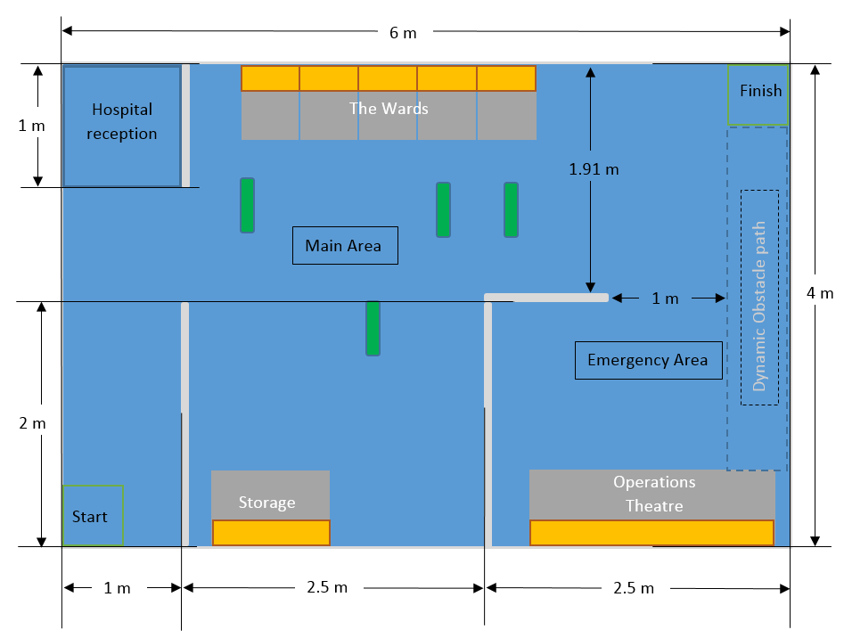
Each year, National Instruments (NI) sponsors a competition to showcase the robotics capabilities of students by building autonomous robots using one of their microcontroller and FPGA products. In 2016, the competition focuses on the theme 'Hospital of the future' where team robots will have to complete tasks such as navigating to different rooms in a hospital setting to deliver medicine while avoiding various obstacles. This project investigates the use of the NI FPGA/LabView platform for autonomous vehicles. The group will apply for the competition in March 2016. More information about the NI robotics competition is found at http://australia.ni.com/ni-arc LabView programming knowledgement would be a key advantage in this project. This project builds on the platform designed and built in 2015
Project Proposal
To have a better understanding of the project and to distribute the workload amongst the team, the robot system has been broken down into the following sections:
- Mechanical Construction
- Artificial Intelligence (Software)
- Robot Vision and Range Finding
- Localisation
- Movement system
- Hardware design
- Medicine dispenser unit
- Pathfinding/Navigation Control
- Object detection
- Mapping Movement tracking
By creating a set of clearly defined work activities, each team member will be able to design and develop the required functionality for their respective sections.
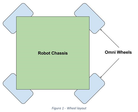
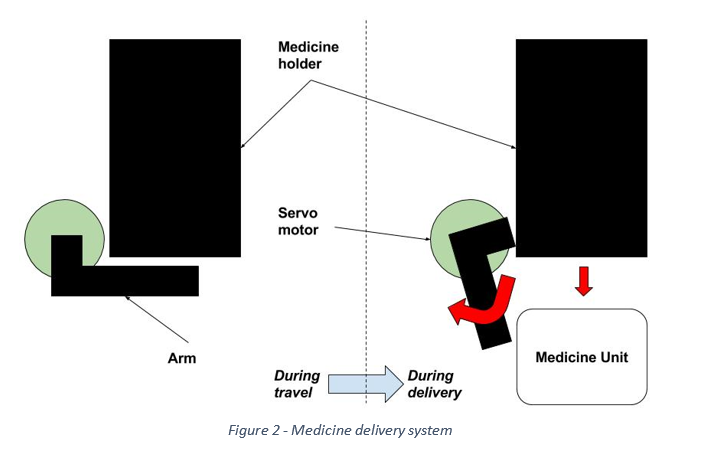
The mechanical construction will focus on the design and assembly of the robot itself. This process will involve deciding on the robot dimensions, motors, sensors and medicine delivery system. Current research and development has been made to the movement system and a four omnidirectional wheeled approach is being prototyped. This prototype will demonstrate a robot with the ability to move in any direction easily without the need to rotate before any translation takes place. Figure 1 shows the layout that will be used for this robot design. The mechanism for delivering the medicine units shall be similar to the design from last year’s University of Adelaide team. Figure 2 demonstrates how this medicine delivery shall work.
The vision and range finding systems for this robot shall consist of an RGB-D camera and an array of ultrasonic sensors. The camera shall be used to implement object detection, while the sensors shall measure proximity to the surroundings. These systems in conjuncture with each other shall allow collision avoidance to be achieved. The localisation system shall be realised through the use of optical flow sensors. These sensors shall measure the direction of flow of the surface below the robot in order to quantify which direction the robot is moving, providing full localisation functionality.
The delivery system, combined with the ease of movement provided by the wheel layout, shall allow for our robot to quickly and efficiently traverse the competition track and deliver the medicine units to the required areas. The use of the mentioned sensors shall provide collision avoidance and localisation, resulting in a robot that can safely and reliably complete the goals required for the competition. In conclusion, this design aims to achieve fully autonomous behaviour in a hospital setting.
Milestones
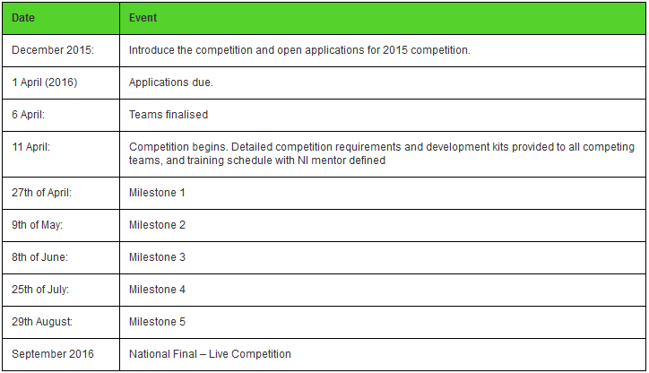
As part of the project the team was required to complete milestones as requested by National Instruments to remain in the competition. The following table summarises the milestones that were completed.
Below is the work that was completed for each Milestone.
- Milestone 1: (27th April)
- Completion of the Online NI LabVIEW Training Course (Core 1 and Core 2) by two team members.
- Milestone 2: (9th May)
- Submit Project Proposal (300-500 words in MS Word or MS PPT format)
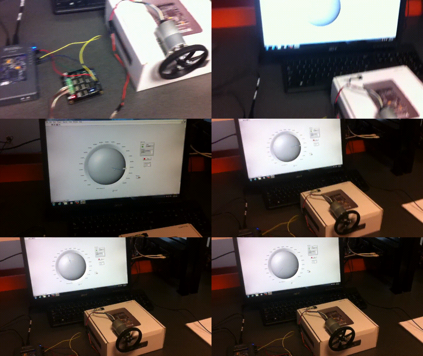
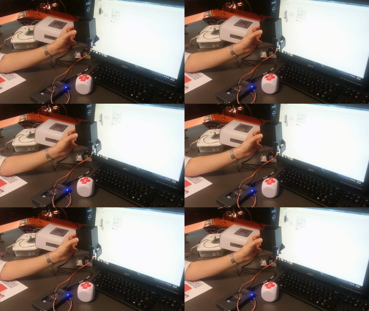
- Demonstrate usage of NI myRIO and LabVIEW to control at least one actuator/motor or acquire from at least one sensor.
- Milestone 3: (8th June)
- Requirement: Preliminary design and prototype with obstacle avoidance implemented.
- Demonstrate: Create a prototype that moves forward avoiding obstacles.
- Milestone 4: (25th July)
- Requirement: Demonstration of navigation/localisation and obstacles avoidance.
- Demonstrate: Robot begins with loaded medicine units in location A and then moves to location B. At location B, the robot carefully places a single medicine unit on an elevated space (a platform higher than the ground the robot is on).
- Milestone 5: (29th August) Requirement to Qualify for Finals.
- Requirement: Object handling, navigation and obstacle avoidance.
- Demonstrate: Move from location A (with loaded medicine units) to location B while avoiding obstacles. At location B, the robot carefully places a single medicine unit on an elevated platform (a platform higher than the ground the robot is on). The robot then moves to location C while avoiding obstacles to place another medicine unit on another elevated platform. Finally, the robot must move to location D while avoiding obstacles to finish the task.
To see any of the above videos in full please visit Team MEDelaide's Channel
Project Outcomes
The outcomes for each of the major systems has been documented below.
Prototypes and Final Robot
Throughout the course of this project two prototypes and a final robot product was developed. Initially, the first prototype was developed as a simple two wheeled robot which the team could use to experiment on and learn from.It was constructed from a single 300 x 300mm wooden base which various wheels and sensors were attached to.
After some research and progress through the early stages of the project a more advanced prototype was created. This version consisted of a 4 omni-wheeled setup. The reason this setup was chosen was to enable the robot to move in any desired direction simply and efficiently.
Finally, after the majority of research was done by all team members and a greater understanding of the capabilities of the previous prototypes the final robot was first designed and then constructed.
To view a more detailed breakdown of the process in designing and constructing final robot please click the link to 'Robot Construction' below.
Movement System
The movement system incorporates all of the control in relation to the motors that turn the four omnidirectional wheels. This control consists of acceleration and deceleration to reduce sliding when starting or ending a movement. It also includes a fail safe which utilises ultrasonic sensors to allow the motor speeds to be reduced or stopped if the robot becomes too close to any nearby object. To reduce the robot veering off course a motor ‘balancing algorithm’ was developed to use the motors inbuilt encoders to determine the distance traveled by each individual motor and scale the speeds of each motor accordingly.
Balancing Algorithm
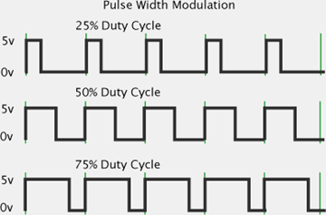
The motor balancing algorithm is the name given to the subsystem which scales each motor’s PWM values automatically while the robot is completing a movement command. Pulse Width Modulation (PWM) is a technique for achieving analog results with digital techniques. Digital control is used to create a square wave where the signal can be switched on and off. A common term used in PWM communication is ‘duty cycle’. Duty cycle is usually expressed as a percentage, it describes the ratio of time spent at a high voltage and low voltage. As can be seen from the figure below the duty cycle of the first sub plot is 25% therefore the signal is high 25% of the time and low 75% of the time.
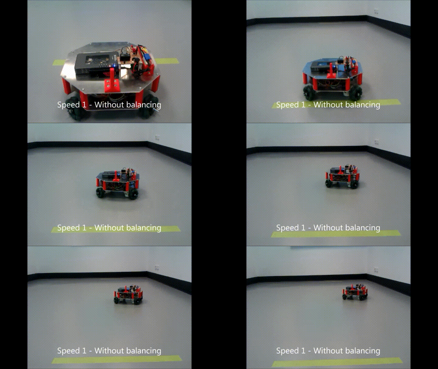
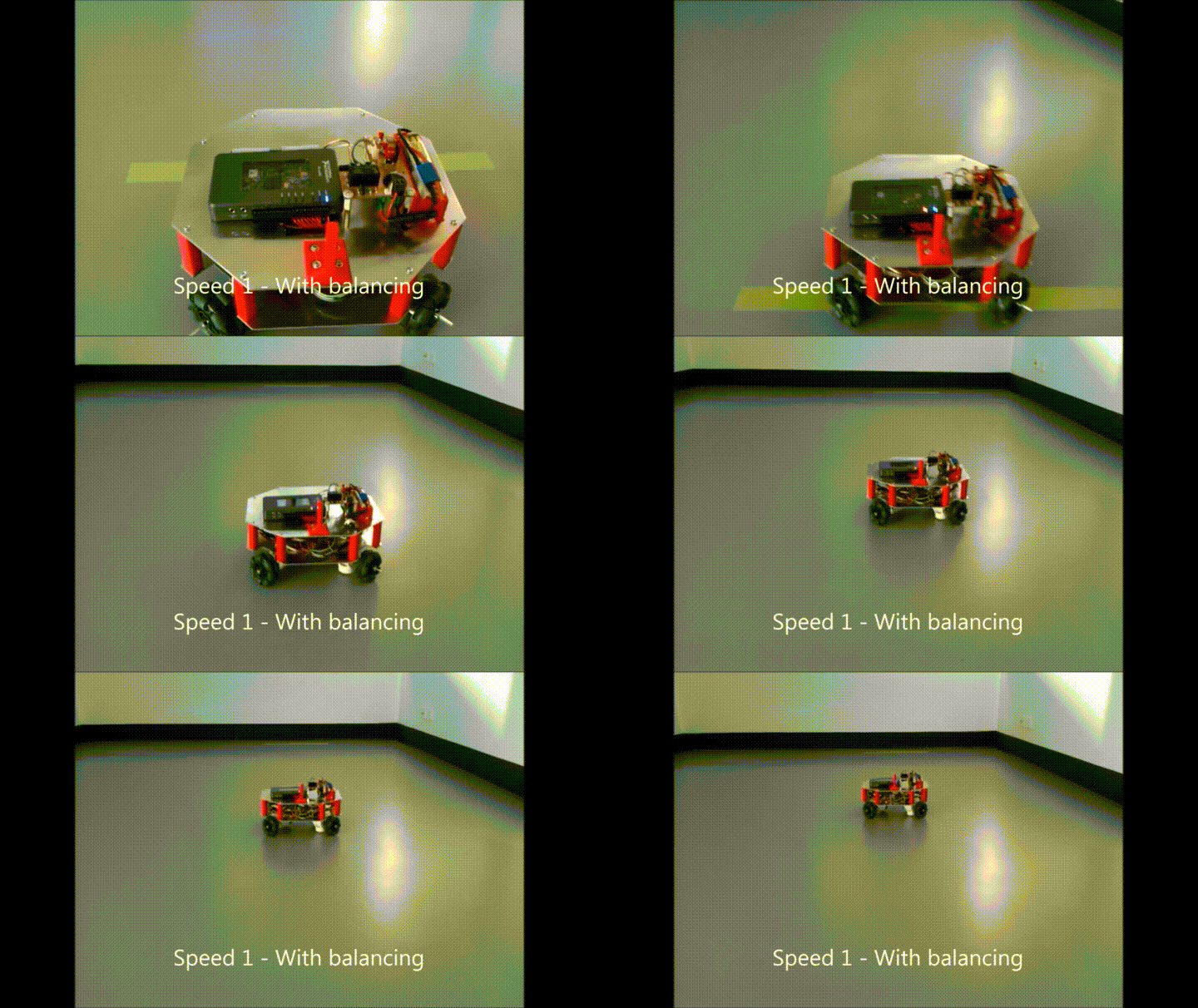
The motor balancing algorithm was invented to reduce the impact of any calibration issues and allow a rough calibration to be performed as the robot is operating. It starts by taking in the current encoder readings from each motor and comparing them to find if the robot is deviating to the left or right of its current path. After the deviation direction is located the motors are scaled either up or down to correct the robot back to the desired path.
The results of this process can be seen in the video below.
Localisation System
The localisation system is built on optical flow, and computer vision. Optical flow provides a high update rate but is susceptible to noise and accuracy drift. Computer vision observations are registered to the competition track. While the update rate is much lower, it has zero drift. A hybrid was built to obtain a fast update rate from the optical flow system, while counteracting drift errors with the computer vision system. Both these components are described in the following sections.
Optical Flow Sensors
Three ADNS-9800 optical flow sensors were used in the project. These use a laser for illuminating the surface meaning higher accuracy than other illumination methods. Also, they can handle speeds of travel up to 3.81 meters per second. This is more than enough to satisfy the robot's top speed (approximately 1 meter per second). A photo of the sensor module is shown here.
The optical flow system was analysed through simulation in MATLAB (see the figure below for an example of the output). This confirmed the drift errors mentioned earlier. Furthermore, it was found that discrepancies between sensor measurements of approximately 10mm was enough to cause heading errors of up to 8 degrees, and position errors up to 46cm and 70cm along x and y in the global coordinate system. This affirmed the need for the drift correction system.
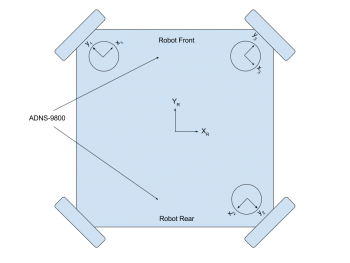
Through testing it was found that the maximum clearance between the bottom of the sensor lens and ground surface is 3mm. This left little room for bumps in the surface area. In order to keep the sensors clear of bumps and maintain a near constant height above the surface, the sensors are mounted directly beneath the motors. Whenever a wheel travels over a bump, the sensor is raised and therefore clears it. To fit the cables attached to the sensor module PCBs, the sensors were mounted with their y-axes pointing out along the axles of the wheels (see the figure below).
Through experimentation with the sensors, it was found that three levels of calibration were required. Firstly, the resolution of the sensors must be found. The resolution is affected by the height it is mounted above the ground, and the angle which the laser projects to the surface. As the sensor height above ground is increased, it's effective resolution is decreased. When the height is decreased, the resolution increases until it reaches the resolution configured in the device. Since the sensors are suspended above the ground, the resolution must be calibrated.
For the second factor, the angle of the laser sensor causes the resolutions to vary depending on the direction of translation. It was found that motion of a fixed distance along the positive y-axis was measured slightly greater than the same distance but along the negative y-axis. This also held true for the x-axis. This result meant that 4 resolution calibration factors were ideally required. In practice it was found that only one per x and y axis was sufficient.
The next level of calibration was for the angular and displacement offsets of the sensors - theta, phi and r components (see the picture below). For higher accuracy these offsets were measured through data collection, and resolving the constants from the 3DOF estimation equation. In this step, the robot was moved in fixed translations and rotations. The algorithm in LabVIEW used this recorded data to solve for the offsets.
The highest level of calibration scaled the translations along the x and y axis as well as rotations to ensure that distances and angles were measured accurately. As hinted in the first level of calibration, the robot's measurements differ between +y and -y translations, and +x and -x translations. These measurements were calibrated so positive and negative movements along the x and y axes were equal.
Using the calibrated offsets and data from the sensors, the position and heading changes of the robot are found using the equation shown below.
Computer Vision System
The computer vision system was built on the range data produced by the Xbox Kinect. See the Xbox Kinect section for more details.
Heading Correction System
As seen in the simulation data previously, the heading of the optical flow system is inaccurate and greatly effected by measurement errors. In practice this was also found to be the case. From testing, the heading was found to be far too inaccurate for use. For instance, the average drift over 1.5m was 30 degrees. The resulting accumulated position errors of the robot were therefore 20cm per meter.
In each case, it was found that while the heading estimation was greatly effected by the measurement errors, the translation estimation was not (see figure (c) in the MATLAB simulation picture above). At this stage, an inertial measurement unit (IMU) could have been added to the system to provide a more reliable source of heading. Due to the competition nearing only one month away, a new tactic involving the Xbox Kinect and motor control was used instead of the IMU.
It was found that by allowing the robot to move without rotations, the robot's position estimation in the robot's local coordinate frame, with a fixed assumed heading could be used. The motor controller managing translations was designed to move the robot with minimal heading changes. To correct for slight heading drifts, and to ensure the robot stays on path, the Xbox Kinect was used to align the robot to key points around the track. More information on the Xbox Kinect alignment can be found in the appropriate section on this page.
Conclusion
The end solution of the localisation system differed from the initial plan in that heading was not measured in the final system, and there was a heavy dependence on the performance of the motor controller. Even with the issues discovered while designing and testing the system, the localisation system was able to successfully measure transnational distances within the accuracy required by the project.
Future improvements for the localisation system would involve;
- Investigate using an IMU for heading measurements, and combine this with the translation estimation from the optical flow sensors.
- Improve the computer vision system to correct position as well as heading.
Vision System
Xbox 360 Kinect Camera
The vision system for this project utilises a Microsoft Kinect RGB-D camera for obstacle mapping and wall alignment purposes. A breakdown of this camera can be seen below on the left, followed by the configuration in which the camera is mounted onto the robot on the right.
This project primarily uses the IR camera output to produce depth readings in a 3D space (see followings subsections for explanation).
Obstacle Mapping
The method for mapping obstacles from the Kinect's depth readings involves two steps: lens distortion correction, and rotation and translation. To see an in-depth explanation of these methods, click here. To demonstrate the outcome of applying these methods using LabVIEW on the myRIO device, a data set was captured of boxes placed in a room corner. The set of images below show: the colour image of the capture (left), the 3D plot of the data created from the IR camera readings (middle), and the corresponding 2D obstacle map.
Wall Alignment
The primary use of the 2D obstacle map is to perform wall alignment rotations in order to correct for heading drift in the movement system. The image below demonstrates how this is realised, with the colour capture of a wall on the left, and the corresponding obstacle map (shown as red data points) with measured alignment angle (shown as black line) on the right.
The movement system can then perform rotations by this measured angle to result in the robot facing the desired wall.
Path Planning
The path planning The development of the autonomous robot is moving fast and plays significant roles in science and manufacturing fields. An autonomous robot is a robot that is able to perform tasks by its own; particularly they are designed in certain areas and fields. The robot is able to perform repetitive tasks while it can make its own decisions to make sure it do not damage any object or human or be damaged in unexpected situations. For example, famous autonomous vehicle NASA Mars Rover Opportunity and Spirit can make their own decisions to make additional observation of rocks by using their camera sensors to check the rocks that satisfy certain criteria.The trending of autonomous robot expands on many fields, such as in logistics delivering goods, military combat situations and manufacture goods. In the future, it is expected that the autonomous robot take over low skill labour jobs, so people can focus in more senior level of work.
Many researchers across the world are working on the path planning algorithm of autonomous robot. Numeral algorithms have been invented and further improved to calculate optimal path(shortest path) from start area to target areas without collision with obstacles. In this Project, pointBug path planning algorithm is used and implemented in LabVIEW for the autonomous robot system.
PointBug algorithm is a point to point path planning algorithm. It plans the path based on the readings from Kinect camera sensor and from start point to target point. The Kinect camera sensor returns magnitudes and angles in the one dimensional array form. Because the readings from Kinect are randomly allocated and cumbersome, a technic of data reduction is used to illuminates all the useless and meaningless data such zeros or NaN(Not a Number) in magnitudes and angles arrays. Next, the order of angles array is sorted so the element from the array starts at 68 degree to 111 degree. Then many similar values are filtered out and only use one of the set of similar values to represent the rest ones. Each element in magnitudes array was corresponding to the element in angles array in the same order. At this stage, the elements in these two arrays are much smaller and all arrays are in order to ease the process for the path planning algorithm.
The robot uses its sensors to check special points called sudden point. A sudden point is a point that the sensor detects change from the nearest obstacle to free space. To help to understand the concept, the figure below is used to explain the sudden point.
The pointBug algorithm checks adjacent value in magnitudes array starting at the first element of the array, which was also corresponding to the first element of angles array.If there was 50cm difference between two adjacent readings from Lidar sensor, then a sudden change was detected. Then the algorithm determined the sudden point by first analyzing which point was closer to the robot between two adjacent sensor readings with 50cm difference between two values. The sudden point was chosen as the point that was further away from the robot and also the closest toward target point. If the sudden point was on the left of the obstacle that had been detected, the robot chose to go to the point more left to travel in order to safely avoid the obstacle, because there were 5-degree gap of Lidar sensor readings and there could be obstacle in the 5-degree gap. In the similar manner, if the sudden point was on the right of the obstacle that had been detected, the robot chose to go to the point more right. If there is no sudden point found, then the robot determines that the target is unreachable and it stops.
However, this path planning algorithm is not used in the project because it needs accurate measure of the current position of the robot from localisation system. It is also found that the assumption of determining whether the target is reachable or not is wrong. The detecting range of the Kinect is only 43 degree, which is considerably small compared to other sensors. The potential sudden point can be at outside of the detaching range of the Kinect camera sensor.
Conclusion
The pointBug algorithm is implemented in LabVIEW and tested to find the correct way point (sudden point ) to travel in order to reach the final destination point. The further work involves letting the robot to turn a certain degrees to get readings from the Kinect sensor to find the sudden point for the robot to travel to avoid collision with obstacle. Until the robot turns 360 degrees, the robot determines that the target point is unreachable and it stops.
References
- ↑ https://www.rmcybernetics.com/blog/basic-pwm-explanation/
- ↑ Microsoft, “Kinect for Windows Sensor Components and Specifications,” Microsoft, 2016. [Online]. Available: https://msdn.microsoft.com/en-us/library/jj131033.aspx. [Accessed 2 June 2016]
